gabriele.vajente@LIGO.ORG - posted 16:02, Wednesday 06 June 2018 (42362)
Beam jitter investigations
[Sheila, Gabriele]
Summary
- we re-centered the IMC REFL WFS and checked that angular beam jitter is the same as what reported in 41940, so the increase in jitter was not due to the WFS centering
- we checked the beam paths on IOT2L and found no evidence of clipping
Then, we increased the input power to 18 W, and looked at IM4_TRANS. There isn't a lot of signal-to-noise ratio, but there is clearly coherence between the jitter as measured by the WFS and the (small) signal measured on IM4. Moreover, the WFS see similar jitter when the IMC is locked and when the IMC is unlocked. Therefore we conclude that
- the angular input beam jitter we measure with the WFS is worse now than during O2
- this is real angular beam jitter, that is measurable in transmission of the IMC, and not due to something that happens in IOT2L
Details
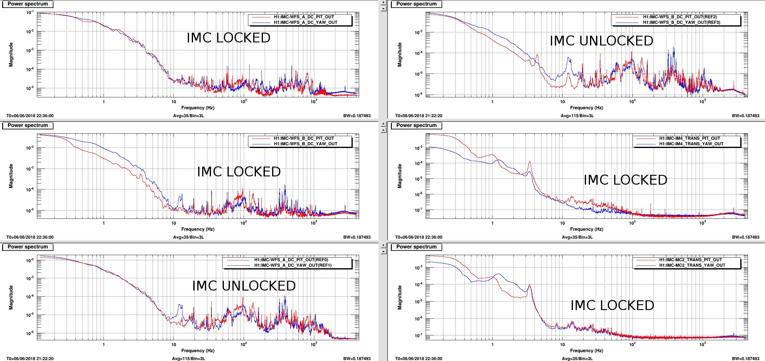
The first of the two attached plots shows:
- The two panels labeled "IMC UNLOCKED" show the WFS spot position signal when the IMC is unlocked, thus having the whole power (2W) going to the IMC reflection
- Two panels labeled "IMC LOCKED" show the same signals as in the previous case (WFS spot position): the structures that are visible here are the same we see when the IMC is unlocked, just with lower SNR
- The other two panels labeled "IMC LOCKED" shows what is visible in IM4 and MC2_TRANS, with higher power. Some structures are clearly visible there
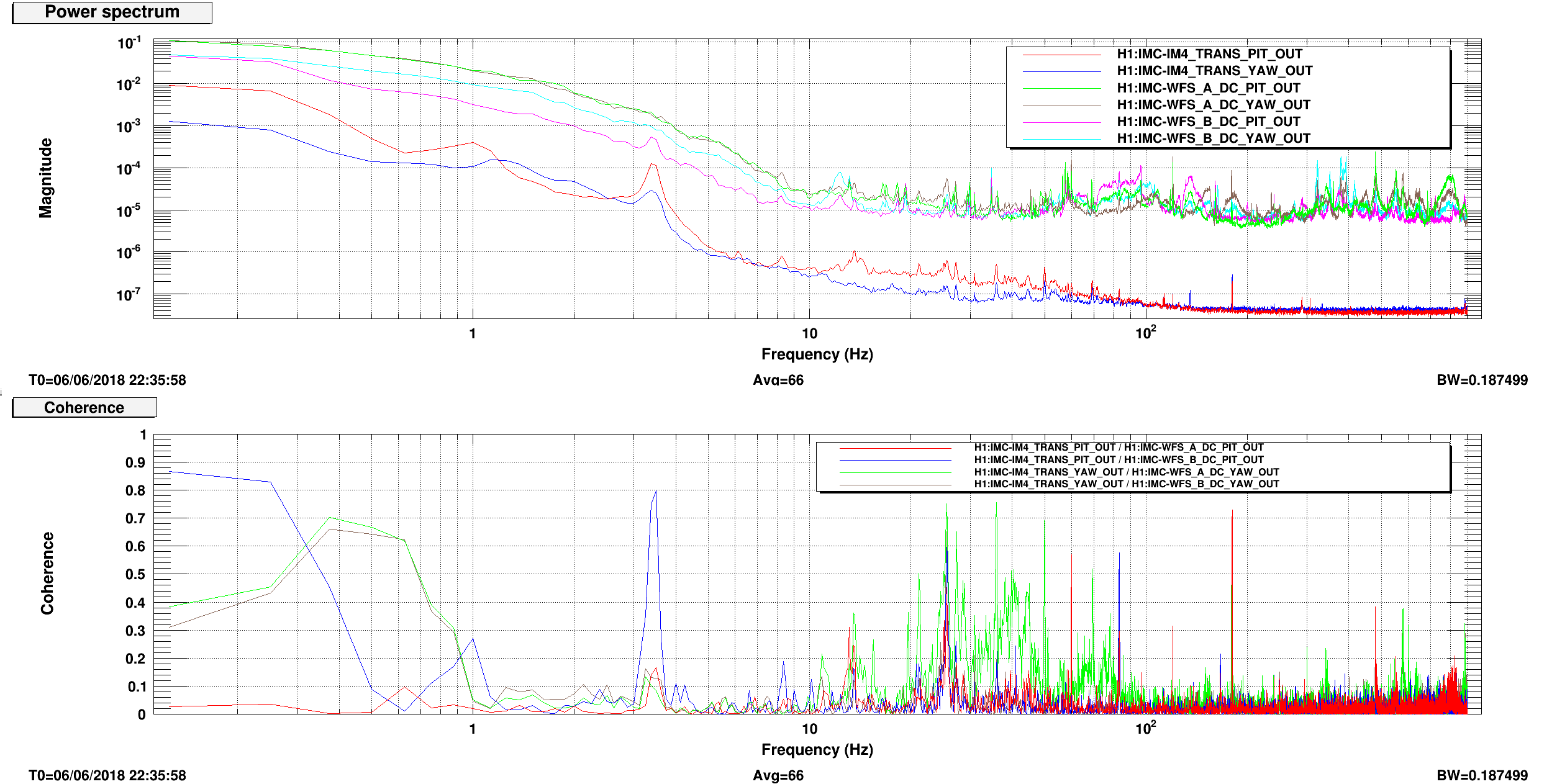
The second of the two attached plots shows that there is coherence between the WFS signals and IM4: the coherence is low, most likely due to the poor SNR in the IM4 QPD signals.
Images attached to this report