Thomas, Sheila, Georgia
Summary
We have calibrated the width, pitch, and yaw outputs of the PSL bullseye PD, accounting for the larger beam size incident on the detector.
We then compared the PSD at the bullseye with the IMC-WFS (on reflection, measured with IMC unlocked) and IMC-IM4_TRANS (with IMC locked) to look for jitter coupling.
The jitter measured by the bullseye PD is 2-3 orders of magnitude below the WFS noise, implying that our jitter does not originate from the 70 W amplifier.
Bullseye PD calibration
Keita reported yesterday on the installation of the bullseye PD, on a pick off directly after the 70 W amplifier stage (alog 42344). TVo and I set about updating the filter banks, which convert the individual segments to width, pitch and yaw, relative to the beam width on the photodiode. We calculated the beam width based on the power on the outer and inner segments, and following Vaishali and Kiwamu's note (DCC-T1700126) calculated the new responses. The new gains are:
g_width = 0.55
g_pit = 0.61
g_yaw = 1.06
Which is only a few percent off the previous gains.
Comparing bullseye PD and IMC spectra
To calibrate the bullseye PD, IMC-WFS, and IMC-IM4_trans such that they can be compared quantitatively, we did a calibration similar to alog 39434 - including the PMC and IMC suppressions, and converting the IMC PDs to units of beam width. The bullseye raw data is multiplied by the PMC and IMC suppressions; the IMC-WFS data is multiplied by the IMC suppression and the factor of sqrt(pi/8) to convert to units relative to beam width, and the IMC-IM4_TRANS data is multiplied by the factor of sqrt(pi/8).
The PMC suppression was calculated from DCC-T0900616, S_PMC = 0.0163. The IMC suppression was calculated from DCC-T060269, and the finesse from DCC-G1400096, giving S_IMC = 0.0039.
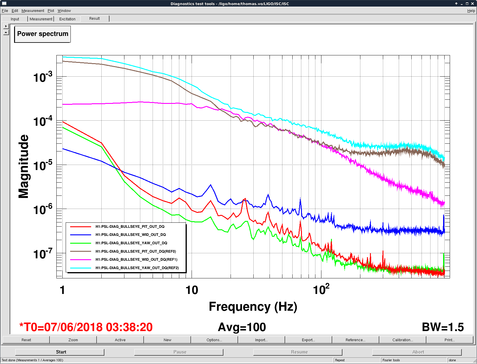
The calibrated plot is attached. The bullseye PD spectra are well below the IMC-WFS (showing lots of jitter) and IMC-TRANS traces.

Attached is the spectra of the bullseye photodiode, now versus O2. The references are from 20170817, which show significantly higher noise in pit, yaw, and wid compared. This supports the idea that the 70W amplifier has much lower jitter motion and the increased jitter seen at the IMC_WFSs (aLOG-42362‌ and aLOG-41947) could be coming from something downstream of the laser.
Somewhat puzzled. The plot indicates that at 10-100Hz the jitter as measured by IM4 is larger than before the IMC, but coherent with the bullseye at the 0.1 to 0.3 level!?
How are the IMC WFS DC signals calibrated? The DC signals are good for measuring jitter, when unlocked. In the past, we had to apply a 1/3 factor when locked, see alog 34845.
I interpreted the plot to mean that the noise on IM4-TRANS is too high to see the jitter. I forgot to mention that the broadband coherence between the bullseye and IM4-trans depended on the incident laser power and looked much higher at low powers. This confused me as well.
Also note in this plot the WFS was measured at ~5W input power (if I've remembered correctly) while the IM4-TRANS was at ~17W input power.
Vaishali/Kiwamu's document calculates dw/w/sqrt(2) instead of dw/w where dw is the beam radius change and w is the beam radius, both at the detector, you need to multiply sqrt(2).
The normalized amplitude of the first radial LG mode that the detector is sensitive to is dw/w, not dw/w/sqrt(2).
I'll leave the check of PIT and YAW calculation to Georgia and Thomas.
If you're interested:
The misunderstanding might have come from some confusion about HG VS LG but I'm not sure.
When the waist size of the beam changes from w0 to w0+dw0 and the waist is displaced by dz, the resulting beam will be expressed by a linear combination of the lowest LG mode LG0 and the first LG radial mode LG1 as
E = LG0 + (dw0/w0+i*dz/zR/2) * exp(i*2*pG) * LG1
where zR is the Rayleigh range and pG is the Gouy phase at the detector. The amplitude of the higher order mode is abs(dw0/w0+i*dz/zR/2), not dw0/w0/sqrt(2) nor dw/w/sqrt(2).
Only the real part of LG1 term is detected as the change of the beam radius when you use DC detector like Bull's eye. pG rotates the complex mismatching parameter and selects the DOF that is measured. For example if pG=0 (detector is at the waist) or +-pi/2 (the detector is in the far field) abs(dw/w)=abs(dw0/w0), and the detector is insensitive to the waist position change to the first order. If pG=+-pi/4 (detector is away from the waist by Rayleigh range) dw/w=-+dz/zR/2 and it's insensitive to the waist size change.
In general, the radius change at the detector is
dw/w=dw0/w0*cos(2*pG)-dz/zR/2*sin(2*pG)
and the detector is insensitive to the orthogonal DOF i.e.
dw0/w0*sin(2*pG)+dz/zR/2*cos(2*pG).
Georgia and I checked the Pit and Yaw calibration for how Vaishali and Kiwamu scaled the units and they are in terms of dw/w which Keita had pointed out is the correct way to compare the bullseyes to the QPD. So we'll change the calibration factor of the width by a sqrt(2) and leave pitch and yaw alone.