[Jenne, Gabriele, Daniel, Keita]
Once the gate valve was opened, we started work on aligning the Yarm to the green beam. Short story: green now locks nicely, we have beam coming to ISCT1, we moved BS to get MICH flashes (with the new ITMY alignment and the ITMX that we've had for a while now), which got us some IR flashes in the Yarm. Team Hartmann (TVo, Craig, Georgia) are now setting SR3 to get the green beam out onto the TCS table.
----------
- Alignment of arm to green
- Baffle PD alignment script worked pretty well for TMS. The TEST filter banks needed to have the urad-to-counts calibration put in, so now the script will do that, so that the moves to the expected PD locations actually work. So, TMSY was set to point at ITMY.
- ITMY was far enough off that the baffle PD script did not work at first. We scanned around (a lot, hundreds of urad) until we saw beam on one of the baffle PDs (#2 at first, which isn't at all close to the optic), then made our way to maximizing the beam on one of the 2 that are close to the optic, setting ourselves close to the center of the optic, then ran the baffle PD alignment script, which worked.
- ETMY was also far off, but again scanning around to find the beam on one of the PDs, we were able to then find the other baffle PD, and put ourselves in the center. We don't have the ETMs available in the baffle PD alignment script, because we don't usually need them. But, sometimes we do need them, so maybe we should add them....if we had infinite time.
- ITMY is now +90 urad in pitch from previous, and -305 urad in yaw from previous. The pitch wasn't so surprising due to the AMD install, but the yaw was unexpected.
- Locking solidly
- Pretty easy - requested Yarm guardian to go to LOCKING_NO_SLOW_NO_WFS.
- There was some triggering that was causing us to lose lock - Daniel overrode / fixed that triggering, and now we're able to stay locked for long periods of time.
- WFS loops closed for Yarm green, camera loop not closed, so not yet full green ASC
- The WFS loops (DOF1, DOF2) for the green ASC closed just fine. They seem to oscillate with the old overall gain value (H1:ALS-Y_WFS_GAIN) of 0.5, but 0.4 is good.
- The camera setpoints are not good any more, so we cannot close the DOF3 loop.
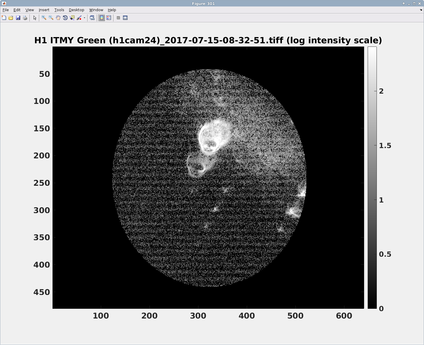
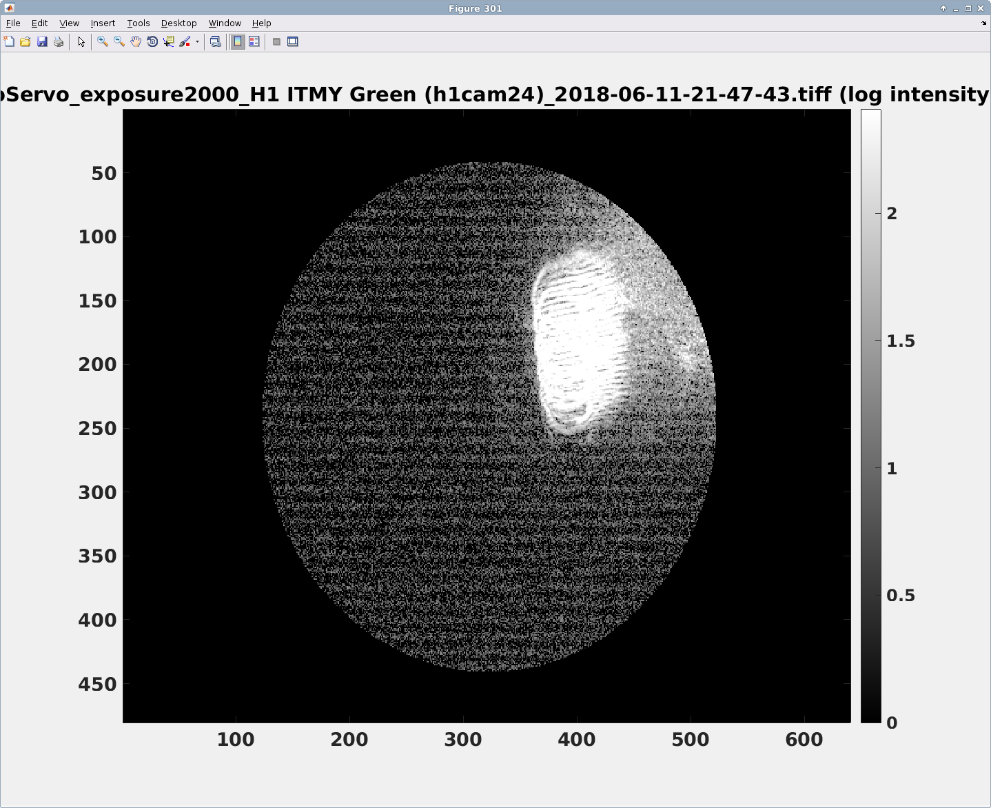
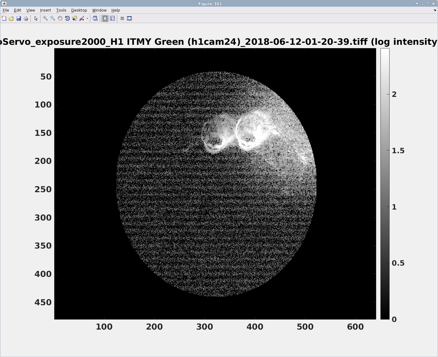
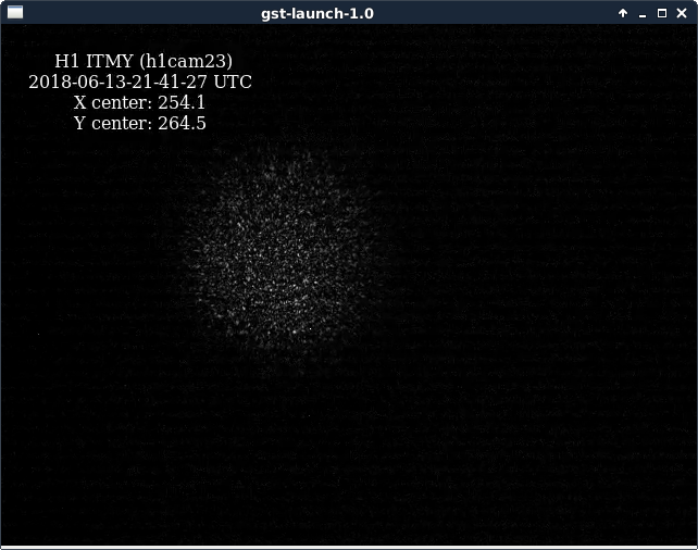
- There is some light coming to the camera that can be moved by moving the compensation plate. Something has always been there (see attached ITMYgreen_old.png), but it seems worse now. As we found it, it was as shown in attachment 2, ITMYgreen_new_prevCompPlatePosition.png. We can move all but the last spot by moving the compensation plate. Because it seems not so nice to have fringes, we've left it at as shown in attachment 3, ITMYgreen_new_newCompPlatePosition.png. Of course, we'll reset the CP later to be good for the IR beam, so this won't be its final final position.
- Once we decide that we're happy with the beam position on ITMY, we can reset the setpoints for the camera, since the one spot doesn't move with ITM position, but the actual beam does. This is what we have done previously, and seemed to work. Eventually, of course, we'd like to figure out where the spot is actually coming from, and prevent it.
- Daniel has calculated that it can't be coming directly from the compensation plate, but we're still not sure where the true source is.
- It's definitely green light coming from the Yarm, since it flashes along with the beam from the Yarm. If the Yarm unlocks, those spots are gone.
- To decide that we're in a good place, we think we'll set the green beam position by dithering ITMY and moving the beam so that it's at the center of the optic. This relies, however, on the coil balancing that JeffK will be doing soon. For now, it should be good enough for Hartmann alignment work.
- MICH aligned, not locked
- Using our new ITMY alignment, and the ITMX alignment that we've been using for the last few weeks, we set the BS to have MICH fringes that we could see on the LSC POP diode.
- We still don't have beam out to the AS port, so we have not yet locked MICH.
- Yarm IR flashes
- Once we restored ETMY alignment (it was misaligned for our MICH work), we started seeing sign of IR flashes in POP DC. We have not yet looked further, since we had other things to work on, but feel reassured that we won't be too terribly far off with our input pointing, once we have the Xarm open.
- Moved PR3 to prevent clipping of beam on ISCT1
- We already have beam at ISCT1, as seen on the ALSY camera. It was clipping a little bit, so I moved PR3 a small amount in both pitch and yaw. There is still some clipping somewhere, but it looks much more similar to what we used to have.
- The Yarm green transmission currently reads a max of 4.4 or so, where the normalization was set to that in O2 the max was 1. This is roughly consistent with what we expect with our new Finesse.
-----------------
Next up for main IFO locking is to move SR2 to get the beam back to the AS port (after the TCS team has set SR3 to get beam out to their table).
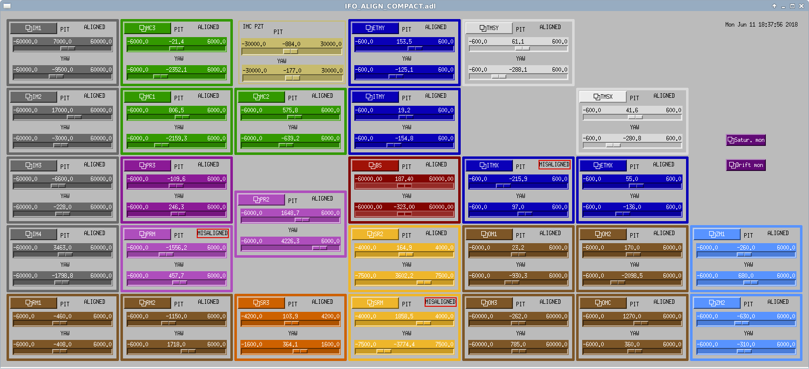
Final attachment is our current slider values.
Methodological comment on MICH alignment
After realigning ITMY to lock the Y arm on green, the Michelson alignment was changed. We were sure about the alignment of ITMY, since it was based on the arm, and decided to keep the alignment of ITMX also as a reference. Therefore the only free degree of freedom left was the BS.
The AS port was completely misaligned, so we had to use POP to look for MICH fringes. We could not see any at first, and we did not have any aligned camera on that beam either.
By misaligning either IMTX or ITMY we could see that both reflected beams were hitting the photodiode: with one mirror only aligned the power on POP was ~2 a.u., while with both beams it was ~4 a.u. Since we could not see fringes we decided to use the following procedure, which we report here for future reference
- misalign ITMY, and move ITMX first in pitch and then in yaw, scanning the range that moves the beam out of the photodiode. We noted the two extreme pitch slider positions that gave us half of the power on POP, then moved to the central value. We repeated the same for yaw. In this way we actually moved ITMX from its good reference, but we had the beam centered on POP
- we misliagned the other mirror, ITMX, and moved the BS to find the photodiode edges as before. We put back the BS in the central position
- at this point we could see MICH fringes, that we optimized by moving the BS, until the power was fluctuating between ~0 and ~8 a.u.
- we still had to move ITMX back to the reference position. To do so, we added a longitudinal 5 Hz dither to BS M2, driving close to railing the actuators. This was enough to induce almost a full fringe motion of MICH. In this way we could move ITMX step by step back to the original reference position, compensating by moving the BS while keeping the MICH fringe good.
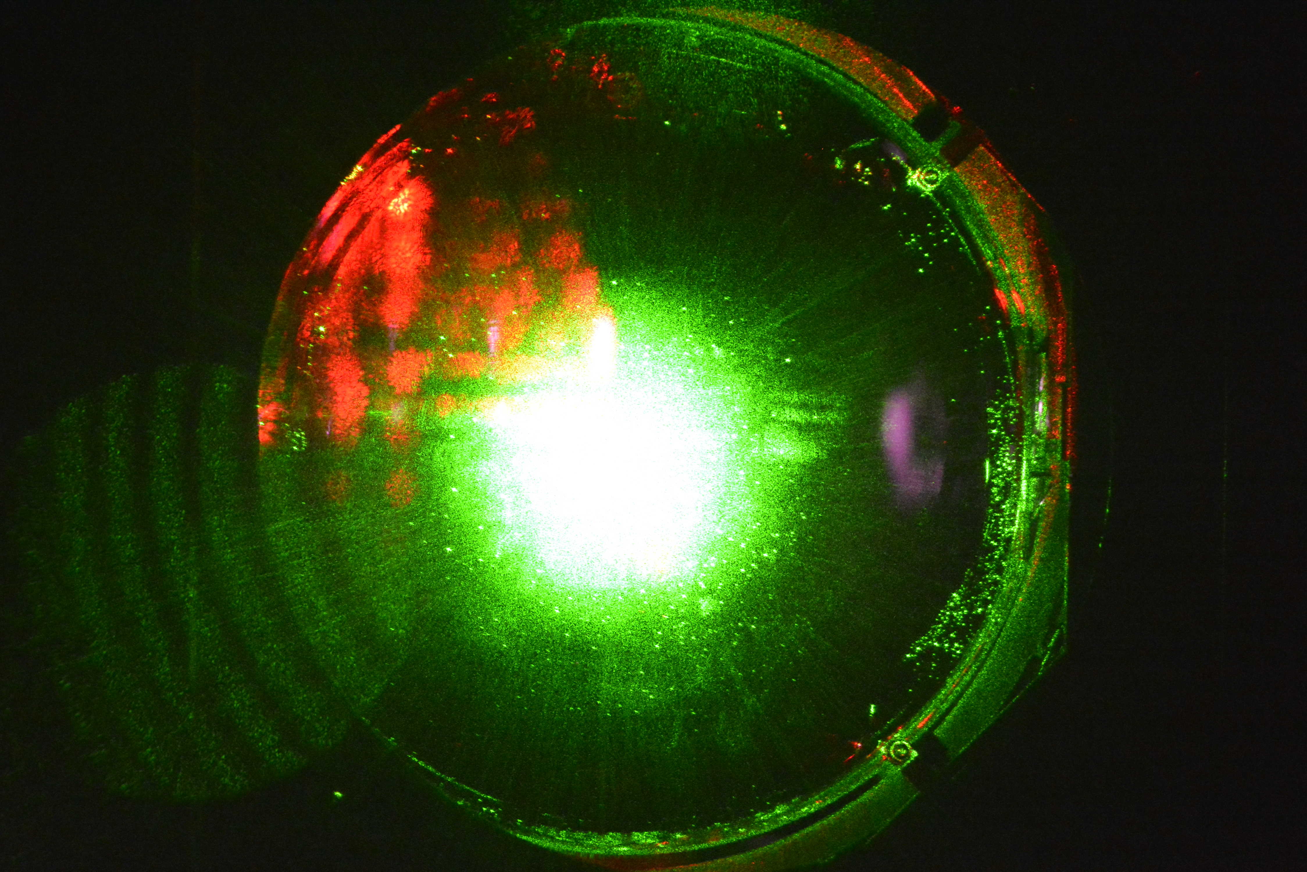
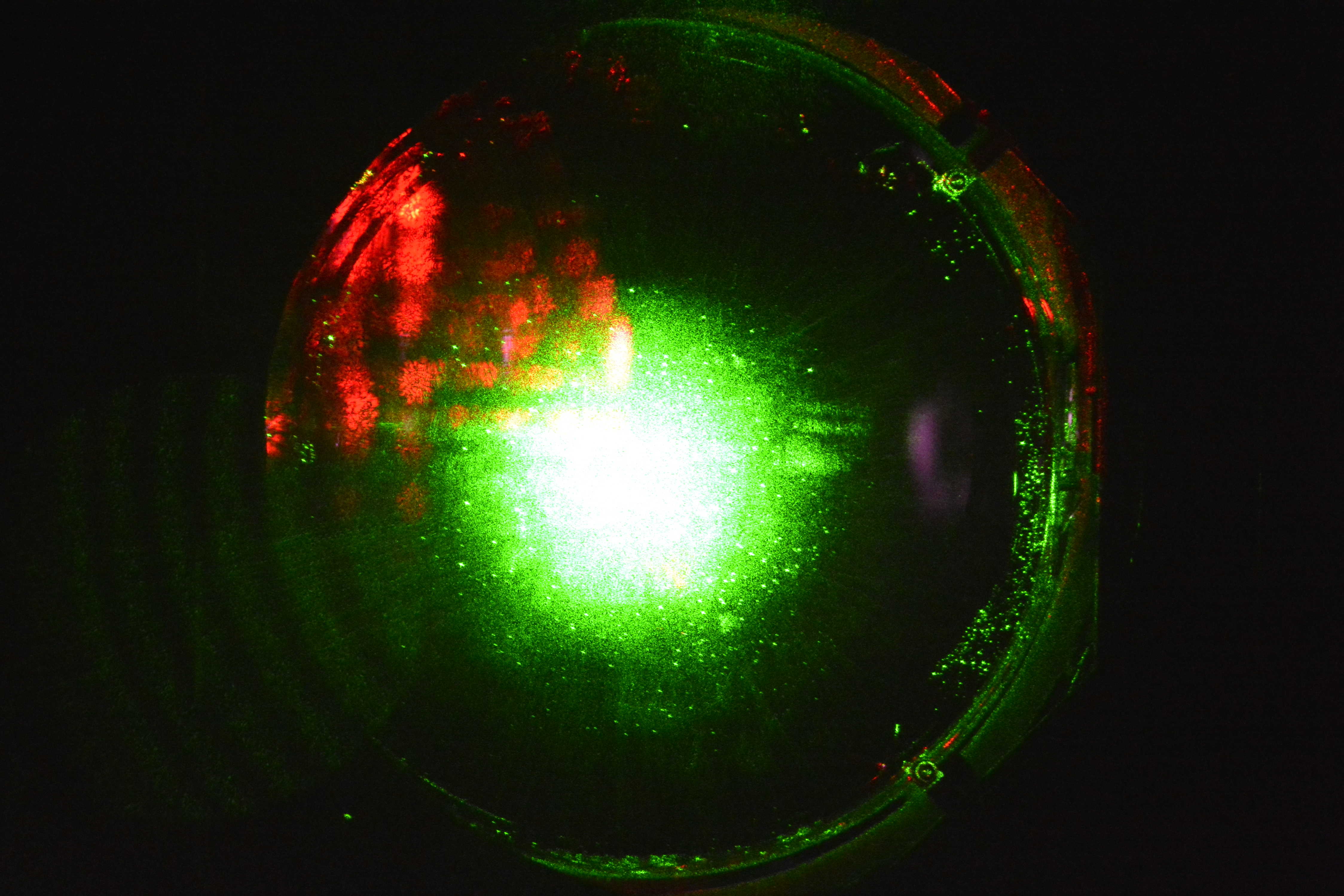
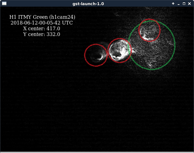
The attached pic shows the full camera frame. The beam circled in green is the ITM HR surface scattering green light back to the camera. The spots circled in red are ghost beams from the rear surface and the two surfaces of the compensation plate. The brightest spot just left of the green circle doesn't move as function of CP alignment where the others do. So, it is most likely the reflection of the ITM AR surface. It is possible to align all red-circled spots on top of each other, at which point we can see a clear etalon effect. One explanation for this picture is that the ghost beams actually hit the camera lens.
The ITM has a vertical wedge with the thick side down. According to D080657 the wedge is 0.07°(+0.03°-0.00°). Taking the largest angle, doubling it and multiplying by the refractive index, we get a ghost beam that is angled down by about 5 mrad. Even after 30m propagation this amounts to only about 15 cm separation. This doesn't seem enough to hit any camera on the Y manifold flange.
PDH locking: From alog 42384 we see that the cavity pole moved from 1.2 kHz to 280 Hz. This is close to the original expectation of 200 Hz. In the common mode board the first boost stage was used to account for the green coating error, whereas the second stage acted as a servo boost. Both are 100Hz/1kHz pole/zero pairs. We locked by disabling all boost stages and increasing the gain by 3dB. The first boost stage now acts as the servo boost. This seems to work fine, but needs a open loop measurements to confirm.
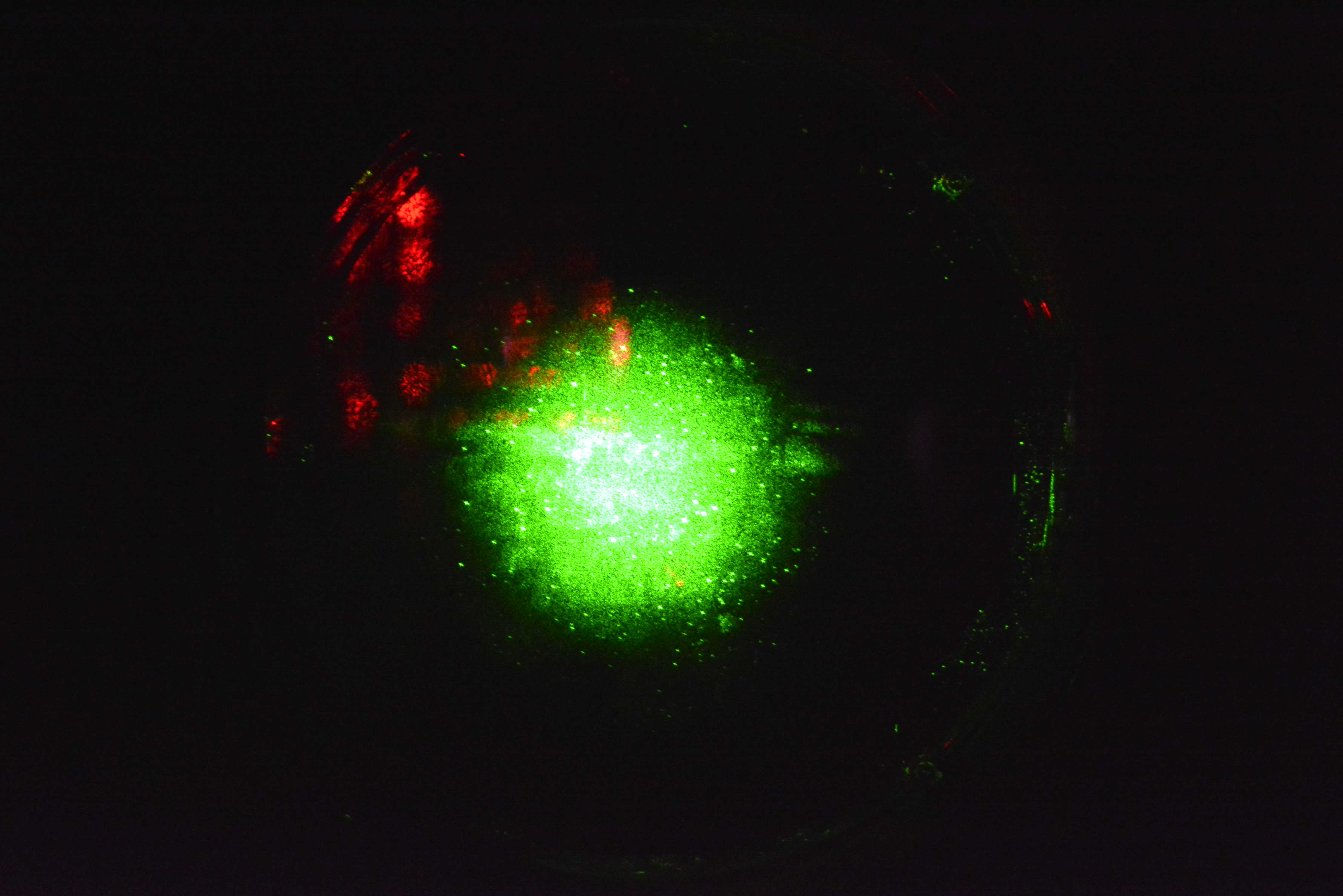
Another pic taken by the "red" camera (mounted on VP6) after it had been resurrected. As it turns out, it doesn't have the green filter installed and is also sensitive to green. None of the ghosts are visible.
Some pics from the high resolution camera taken by Jeff B. Redish stuff is due to the oplev.