WHAT:
-- Using the PRM M1_L2P & M3_L2P filter banks to locally reduce the PRM pitch motion due to the longitudinal cross-coupling.
WHY:
-- More robust lock (as demonstrated at LLO; G1701848).
-- Reducing CHARD control which has been shown to be largely coherent with PRCL control (G1700414; presumably the coupling is due to PRCL -> PRM pitch -> CHARD pitch).
RESULTS:
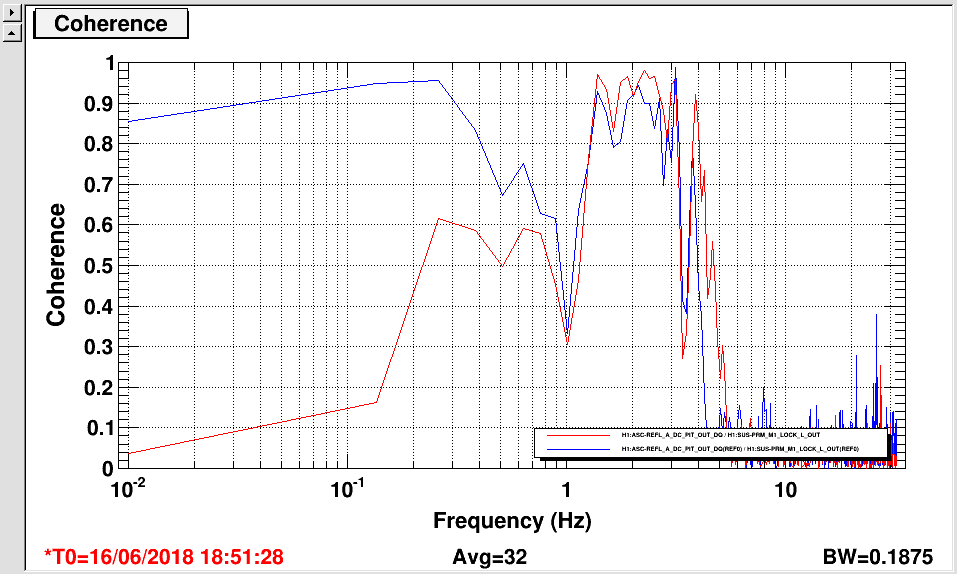
-- First figure: M1L -> M3P decoupling. The blue trace is before engaging the L2P feeding-forward and the red one is after. The L2P coupling is greatly reduced <0.1 Hz.
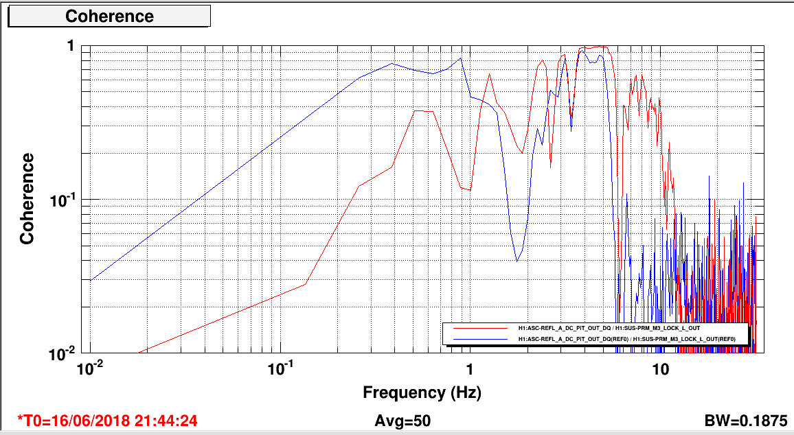
-- Second figure: PRCL -> M3P decoupling. Here we excited the M3_LOCK_L and let the signal go through the whole sus chain (i.e. with the signal offloading to M2_LOCK_L and M1_LOCK_L; in M1_LOCK_L the FM2, 4, 6, 8, 9, 10. This should be similar to the real PRCL actuation in O2). The blue trace is without ANY L2P, and the red one is after engaging both M1_L2P and M3_L2P. By doing two stages feeding forward we should be able to remove PRCL coupling up to 1Hz.
-------------------------------------------------------------------------------------------------------
MORE DETAILS:
As Peter pointed out, my previous measurement using the M3 osem sensors to indicate the M3 pitch was inaccurate because the sensors were not well balanced. We thus redid the measurement using REFL_A_DC_PIT to measure the M3 pitch motion.
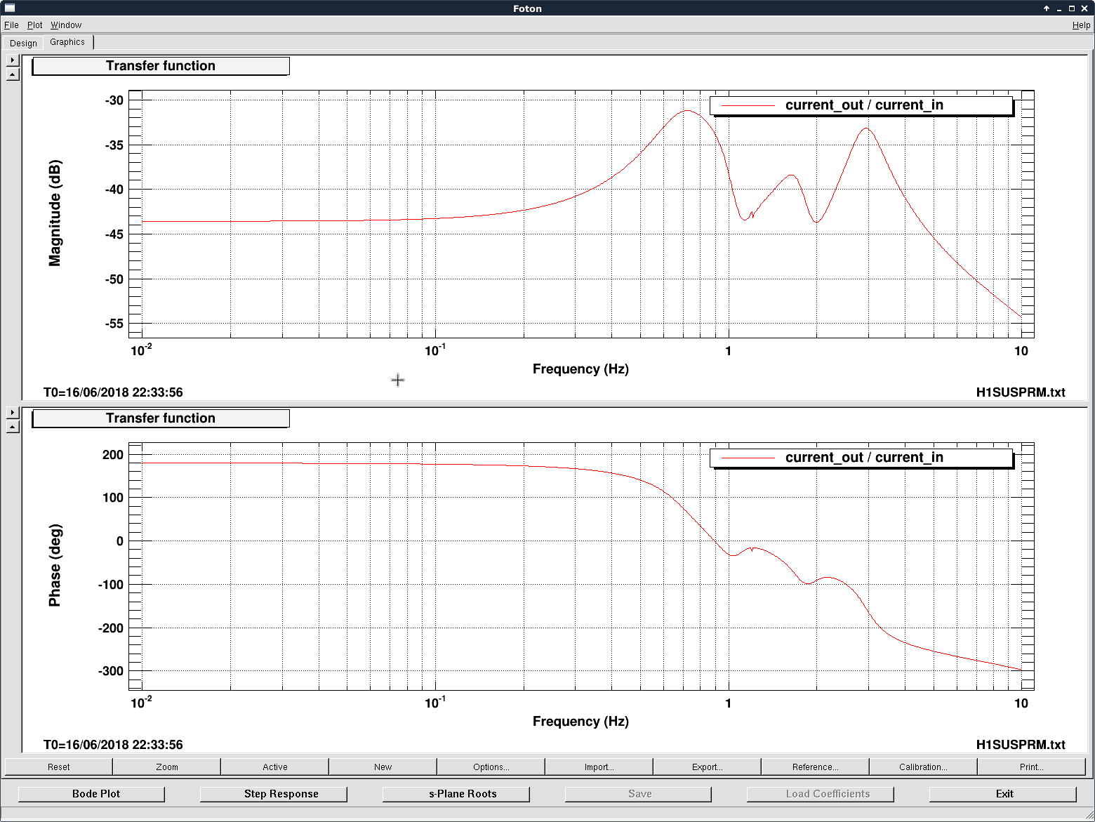
We first excited only M1_L and focused on the <~ 0.3 Hz band. We then put (M1L->M3P)/(M1P->M3P) in the M1_DRIVEALIGN_L2P filter bank (FM2 & 4; it should be engaged with a dc gain of -1). The result was shown in the third figure. Note that here we only inverted the main resonance of M1P->M3P and left the rest of the plant as a natural low-pass filter to avoiding injecting excess noise.
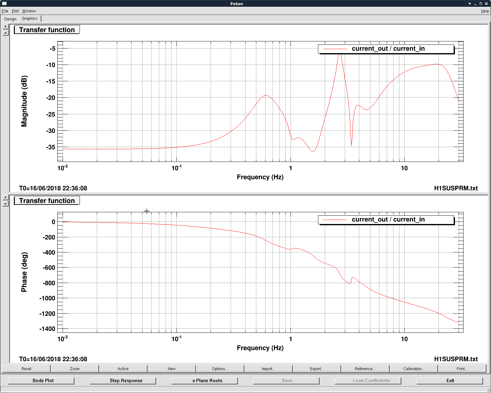
Then we excited the M3_L stage with a signal offloading chain mimicking the O2 actuation setup. We also turned on the new M1 stage L2P FF in the process, and measured the residual L2P coupling in the 0.3 - 1 Hz band. The resultant (PRCL->M3P)/(M3P->M3P) was put into M3_DRIVEALIGN_L2P filter banks (FM6 & 8) and attached as the forth plot. I did not put a very aggressive low-pass above 1 Hz because I thought it would be more important to get good subtraction below 1 Hz than to avoid injecting PRCL noise to PRM in the 1-10 Hz band.