We did some more ETM L2A decoupling work today.
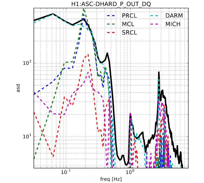
The motivation was that in O2 a large coherence between DHARD ctrl output and DARM ctrl outpu was observed, see the first attached image (for more LSC to ASC coupling during O2, click here). Here the black trace was the total DHARD ctrl output, and the dashed lines were the LSC channel outputs' projection using a freq-domain MISO coherence estimation. We hoped that by doing better L2A decoupling in the longitudinal actuation side, we could reduce the required ASC ctrl bandwidth, which would further reduce the ASC noise in the GW band.
Earlier this week we had done the L2A in the L2 stage. It reduced the coupling around the sus resonance ~0.5 Hz. However, as indicated in the first figure this was only a small contribution to the total DHARD RMS. We thus tried to optimize the L2A in the upper stages.
In the second figure we showed the resultant M0 L2P decoupling. The (black, blue, and red) traces corresponded to (no L2P feeding forward, original L2P, and new L2P), respectively. The new filter should had a broad band improvement relative to the old ones, especially for the sub-0.2 Hz band where about half of the total DHARD RMS was accumulated.
===========================================================================
We further tried to do the same thing for the L1 stage, however, we noticed that
the ETMX L1 stage coil might not be correctly connected?
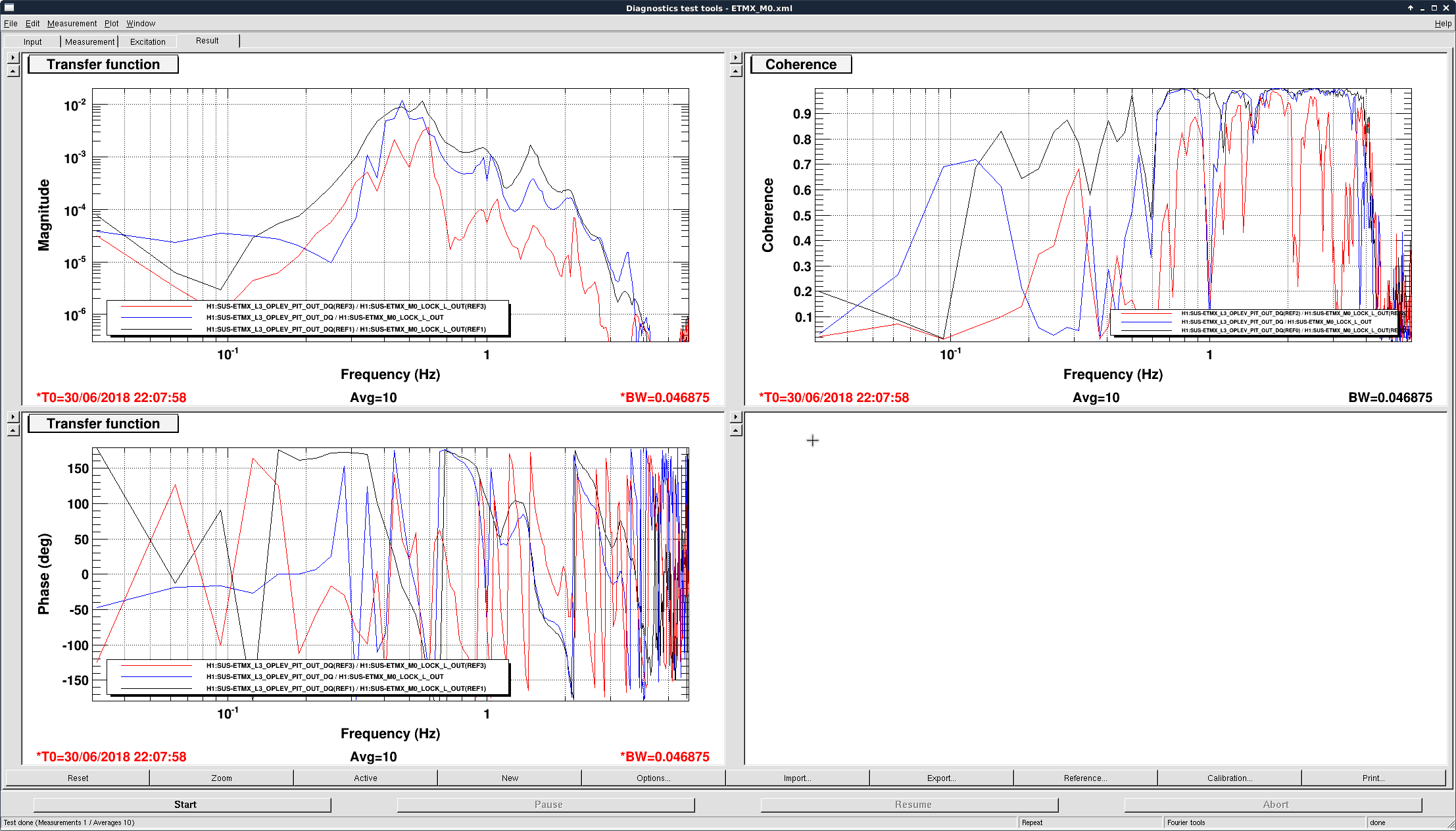
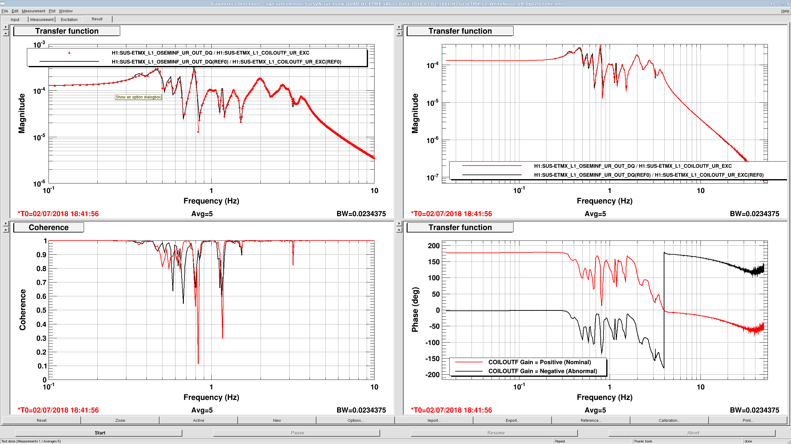
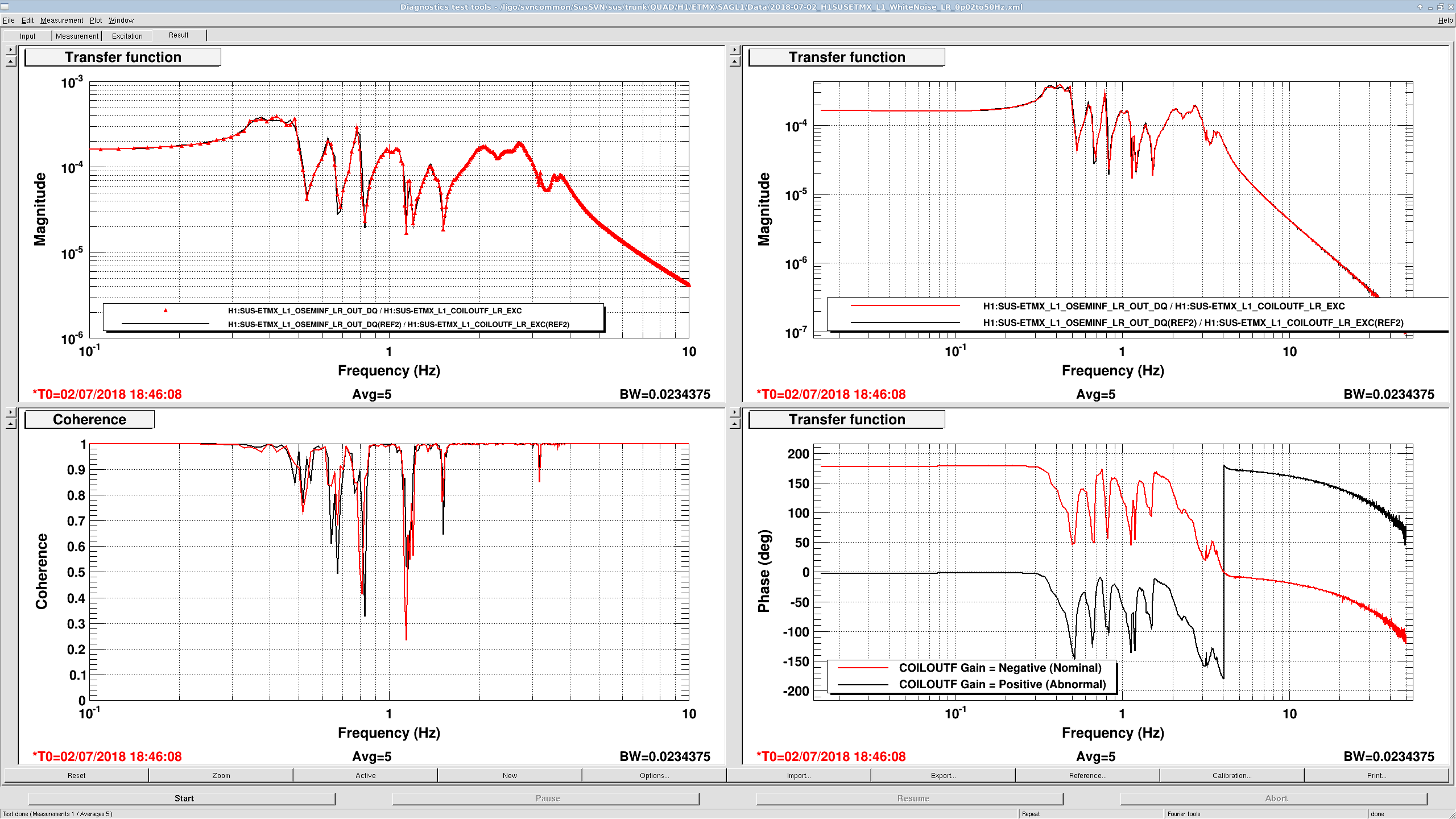
When we excited L1 in length, we saw that the oplev responded mostly in yaw but not pitch. Furthermore, when we excited L1 in yaw, the oplev moved in pitch (as shown in the third image), while an excitation in yaw moved mostly in pitch... This seemed to suggest some issue with the coil connection there.
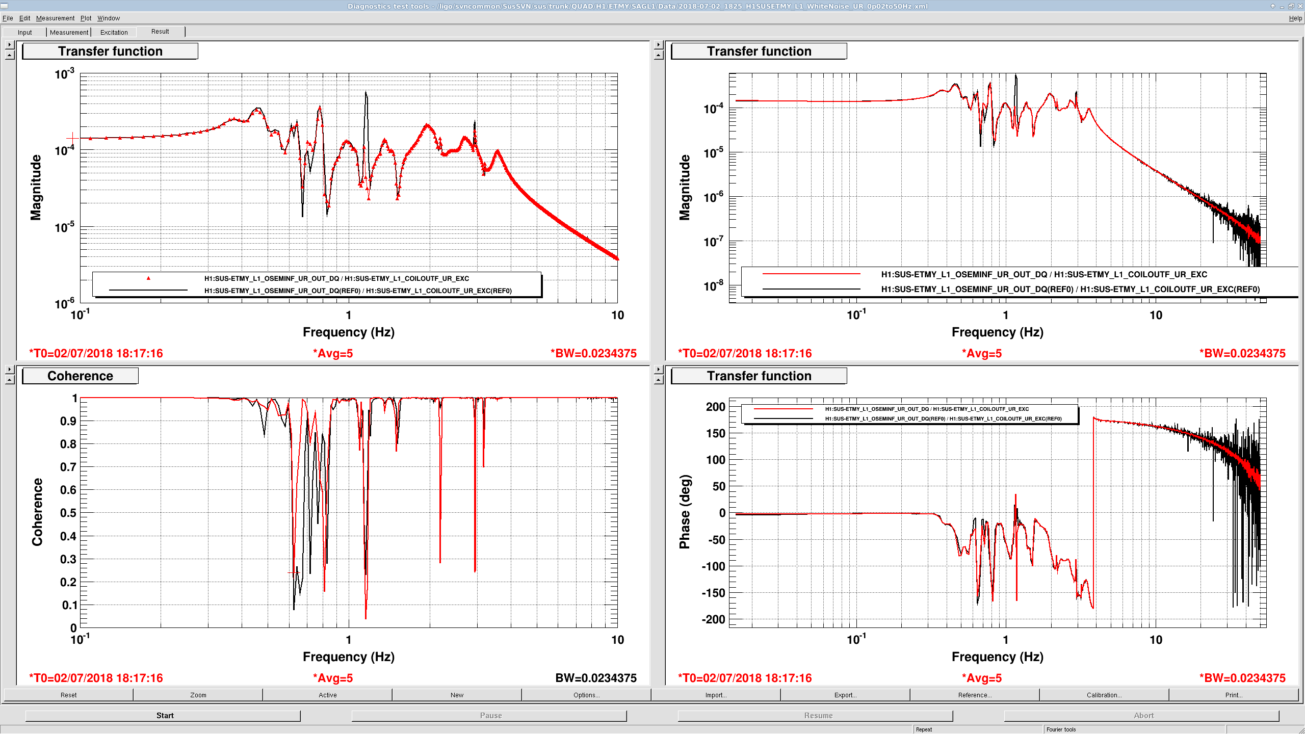
We then checked the same thing for ETMY (which was used for DARM actuation in O2). The oplev in ETMY was not available so we used the L2 stage osem sensors. For EY it seemed that L1 stage was okay in that pitch was pitch and yaw was yaw.
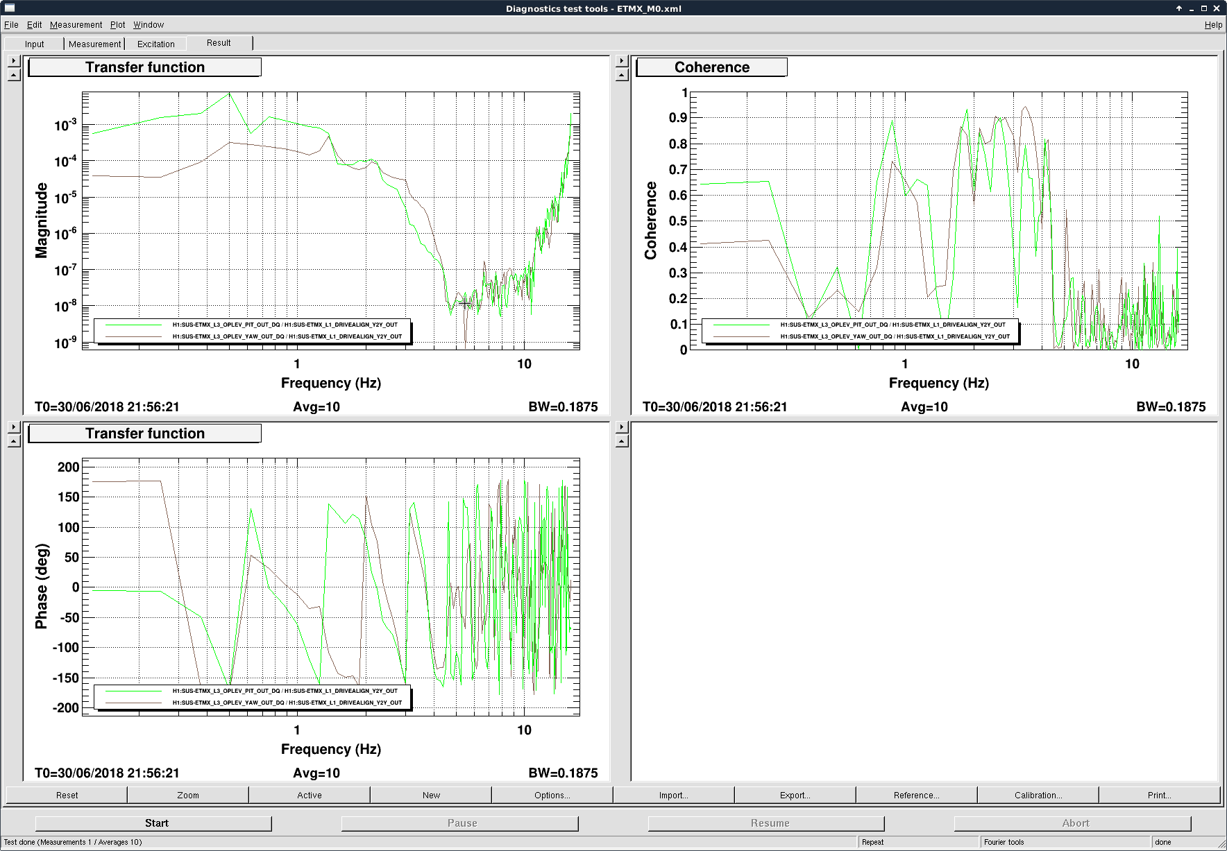
I quickly confirmed that ETMX L1 polarity is flipped for UR and LR coils.
In the attached, OL was centered using M0 TEST offset, ESD off, then +50000 offset was turned on and off for UL, LL, UR and LR coil output filters in this order. Look at the Euler matrix and oplev response sign, they should agree.
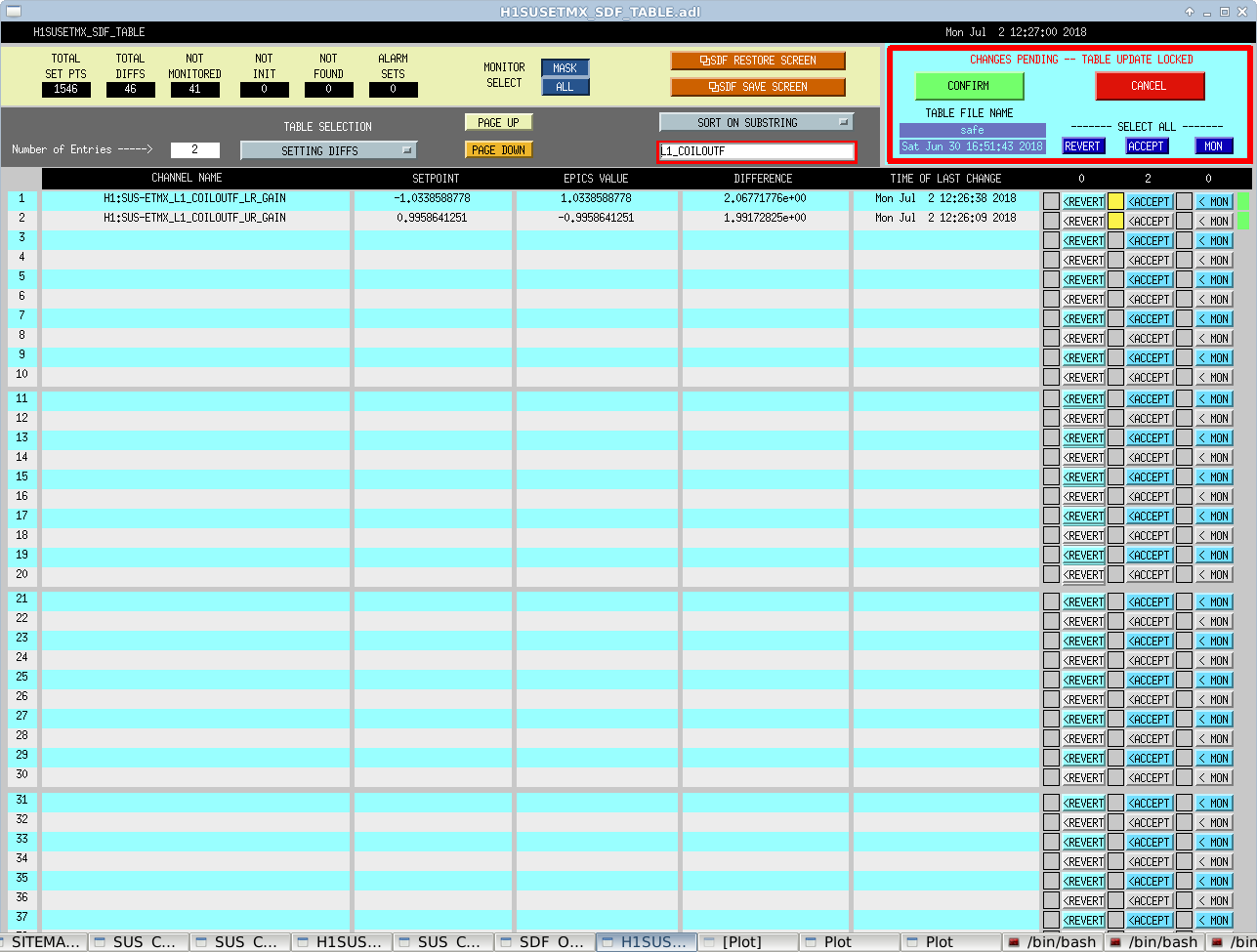
I flipped ETMX L1 coil output filter sign for UR and LR (screen shot is before the change).
If this means that the magnets are physically flipped, YAW coupling to external magnetic field should be much stronger for this guy than others.
Opened FRS Ticket 10993.
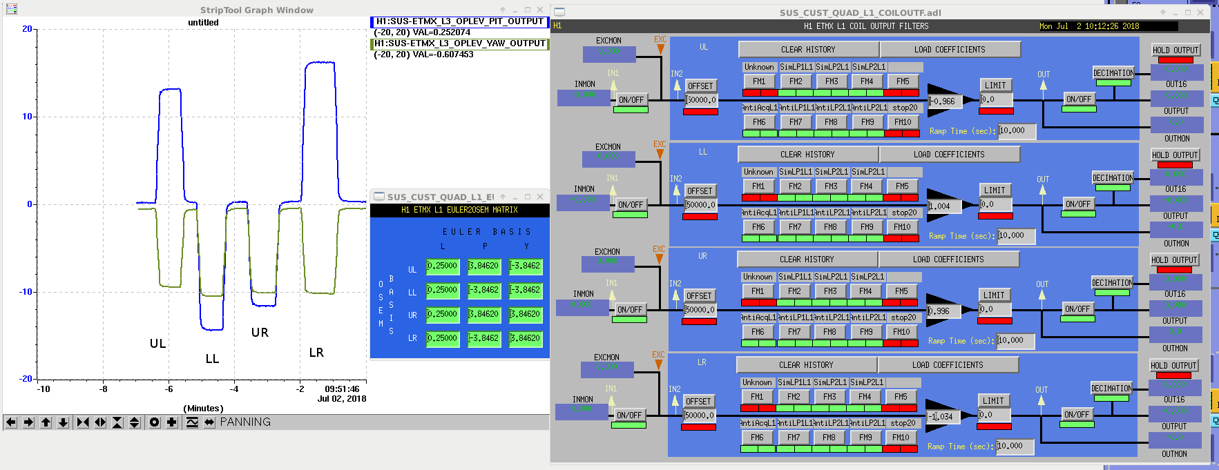
J. Kissel

I've confirmed Keita's conclusion that H1 SUS ETMX's L1 stage's UR and LR actuation chain require a sign flip from the established convention (see T1200015), which compensates for the UIM magnet polarity as defined in the QUAD's controls arrangement poster (see E1000617).

I've done so by taking a (rarely, if ever) set of TFs -- OSEM basis to OSEM basis measurements, comparing the phase with the nominal, conventional COILOUTF gains against the flipped sign that make the chain behave as desired. One can clearly see that the phase starts at 180 degrees with the conventional sign.
I also show the same TF from ETMY which has the conventional signs. ETMY is well behaved.

Yuck!

I've also confirmed with Travis and Betsy that they *do* pull off magnets and cables of these chains during the removal and restoration of the QUADs, so it is indeed plausible that a mistake was made.


I'm reasonably and regretfully confident that -- all other elements being the same as O2 (coil driver, sat-amp, ADC / DAC, AA / AI, etc) that a sign flip can only result from an in-vacuum problem.

Thus, I'm going to close the FRS Ticket as a "LONGTERMFIX" and open a "WHENVENT" ETMX Integration Issue. For now, I've captured the sign flip in the SDF system so that this temporary solution sticks.

Note that, if it is a magnet flip, then this stage will be more susceptible to ambient magnetic fields. Perhaps Robert can confirm with a future measurement compared against O2 once we get an IFO back up and running.
We will check the coupling due to this double flip, but since it was two magnets that were flipped, I dont necessarily expect more environmental coupling. Cancellation should still work under the (wrong) assumption of uniform fields and gradients; the coupling may go up or down depending on the differences in fields and gradients between magnet locations.