Stefan, Danny, TVo
Today we decided to take a more careful approach by setting up a red cross-hair laser and coalign the alignment laser with the CO2 beam on the two irises before the periscope.
We then found that the beam was clipping on the small aperture which is formed by the double ZnSe viewport and decided that the periscope structure had to be moved in order to avoid clipping and center on the top periscope mirror as well as get to the CP. However, to avoid losing the alignment completely, we installed a camera with a zoom lens to see the CP through the visible viewport, this proved to be extremely useful. We then slid the periscope structure and bottom periscope 1.5 inches in the +y direction (IFO coordinates) and re-aligned using the camera.
After a bit of fine tuning with walking the beam, the result is a much cleaner beam as shown by the Hartmann (Stefan will comment)! Hopefully at this point, we won't need to go back on the table and can do the pointing adjustments with the top periscope picomotor. One interesting thing about the annulus heating, not much of it gets through the viewport.
Attached are figures of the end result:
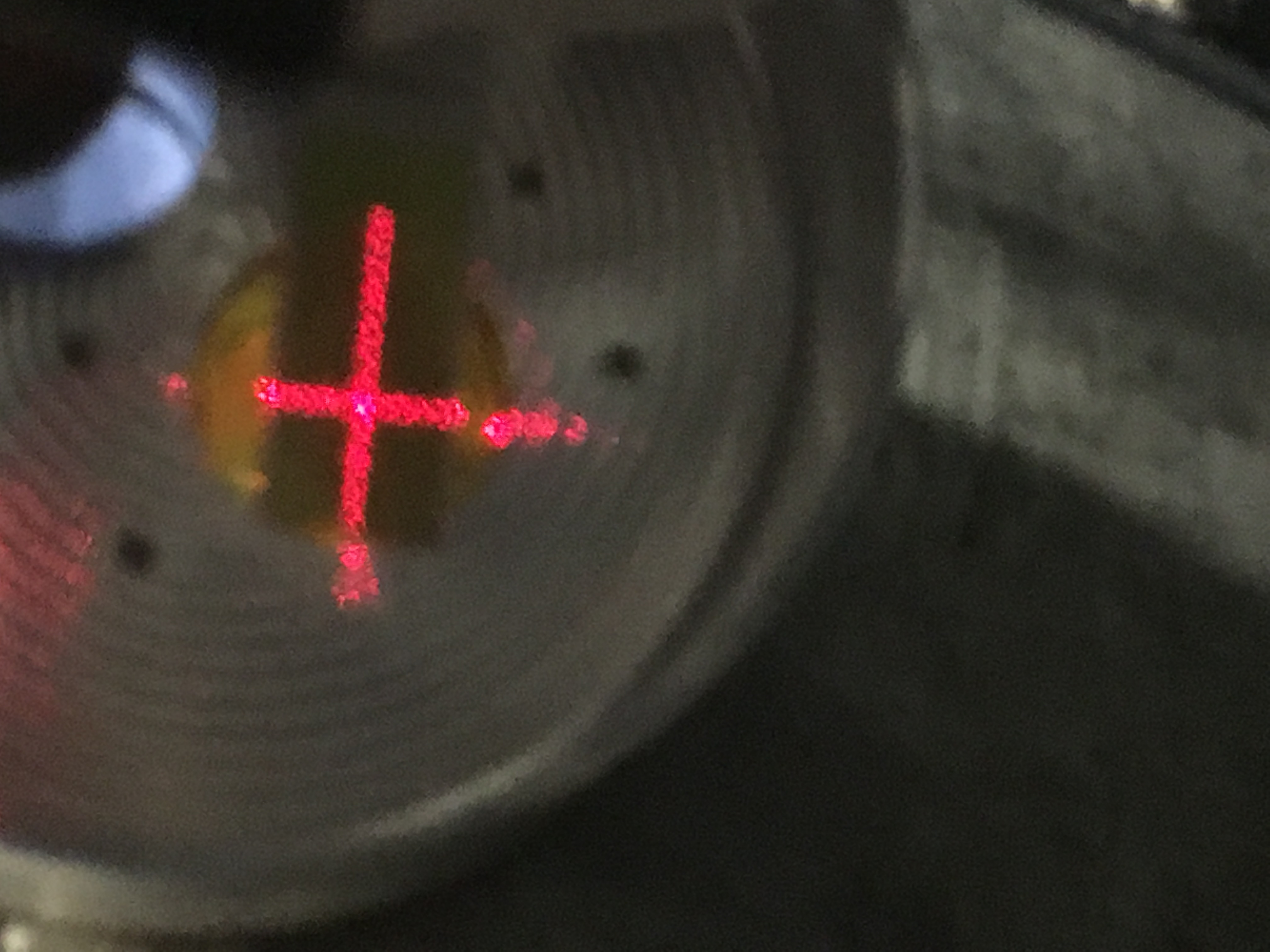
Fig 1. Cross hair on the viewport
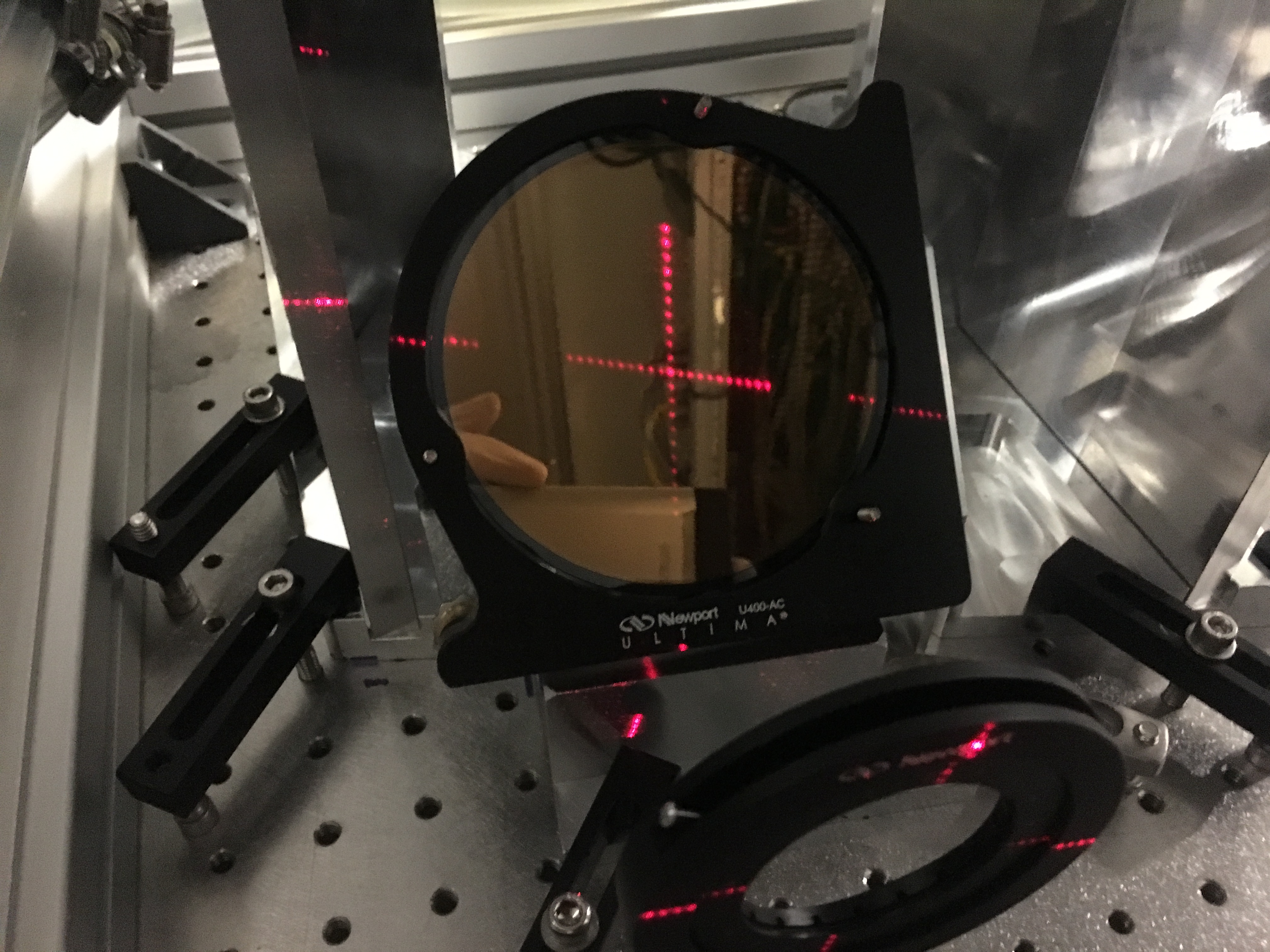
Fig 2. Cross hair on bottom periscope
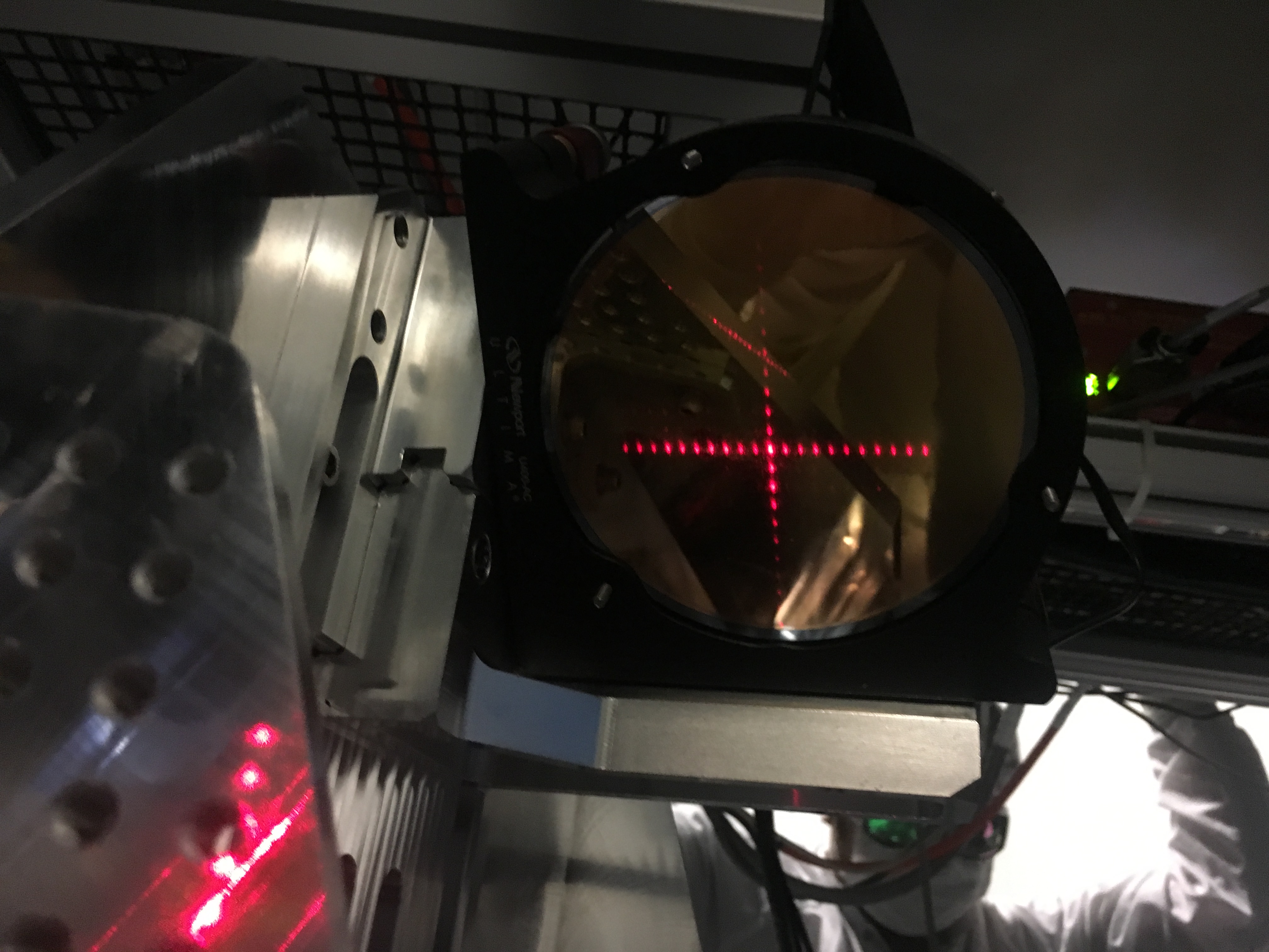
Fig 3. Cross hair on top periscope
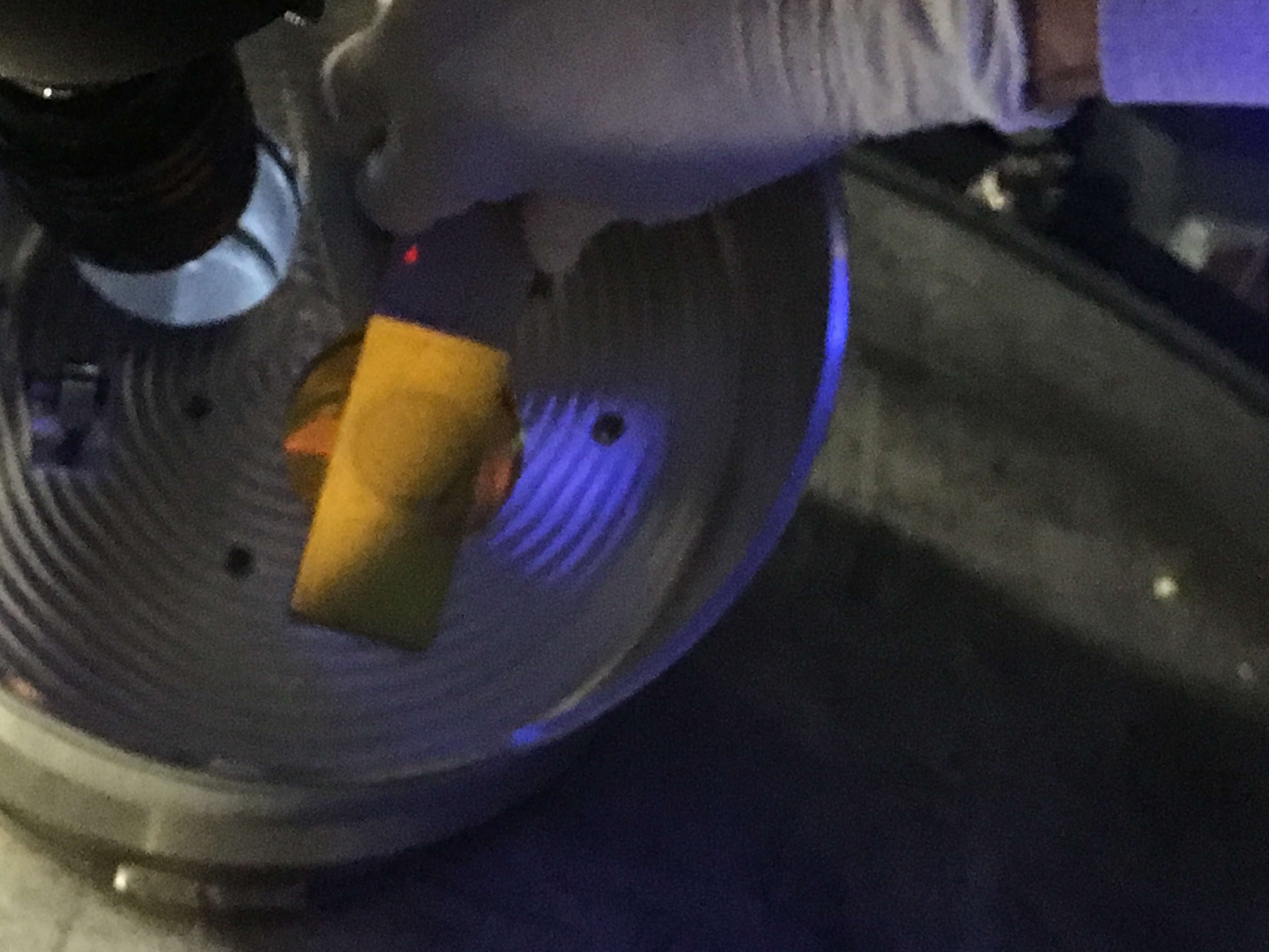
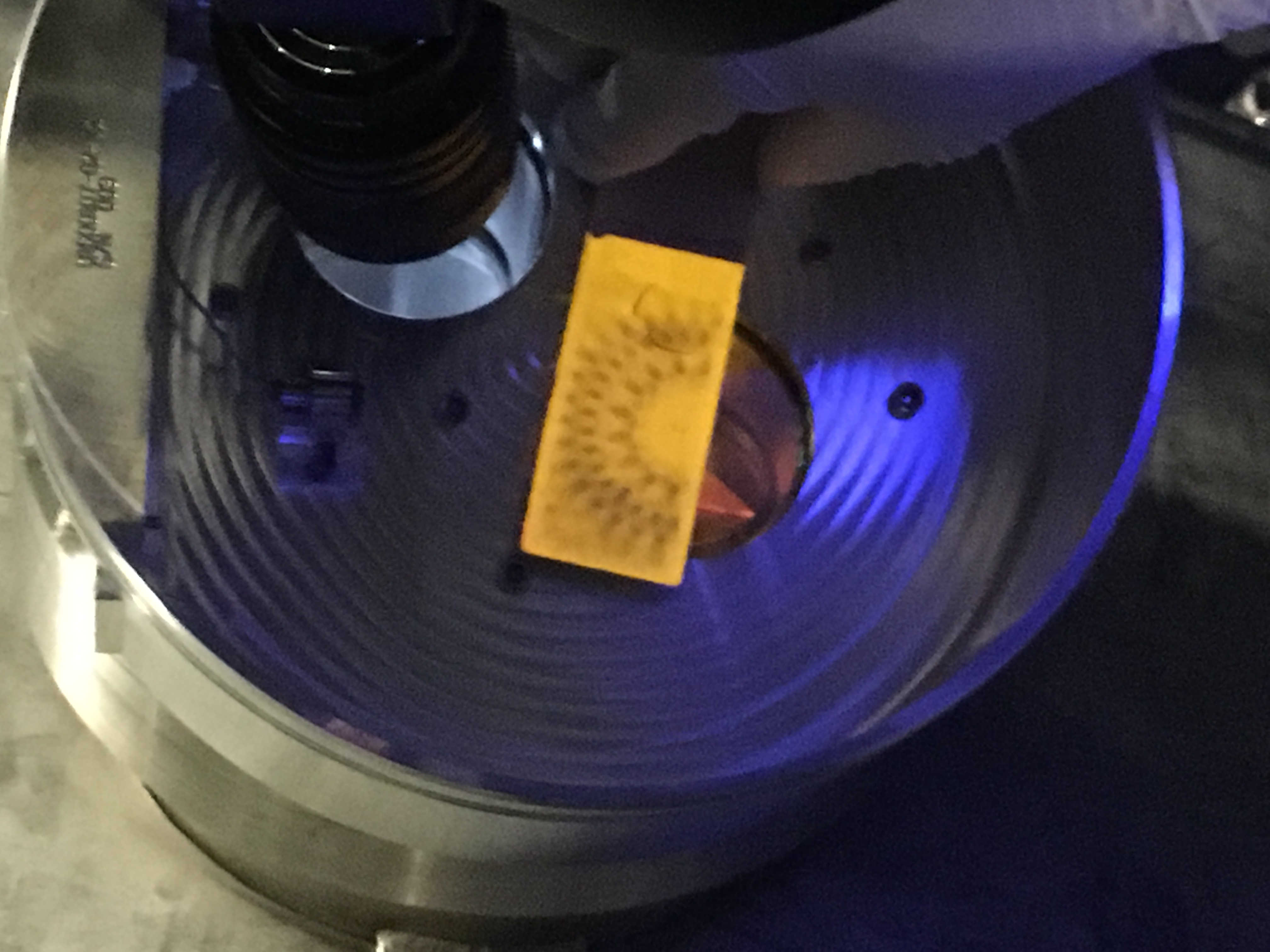
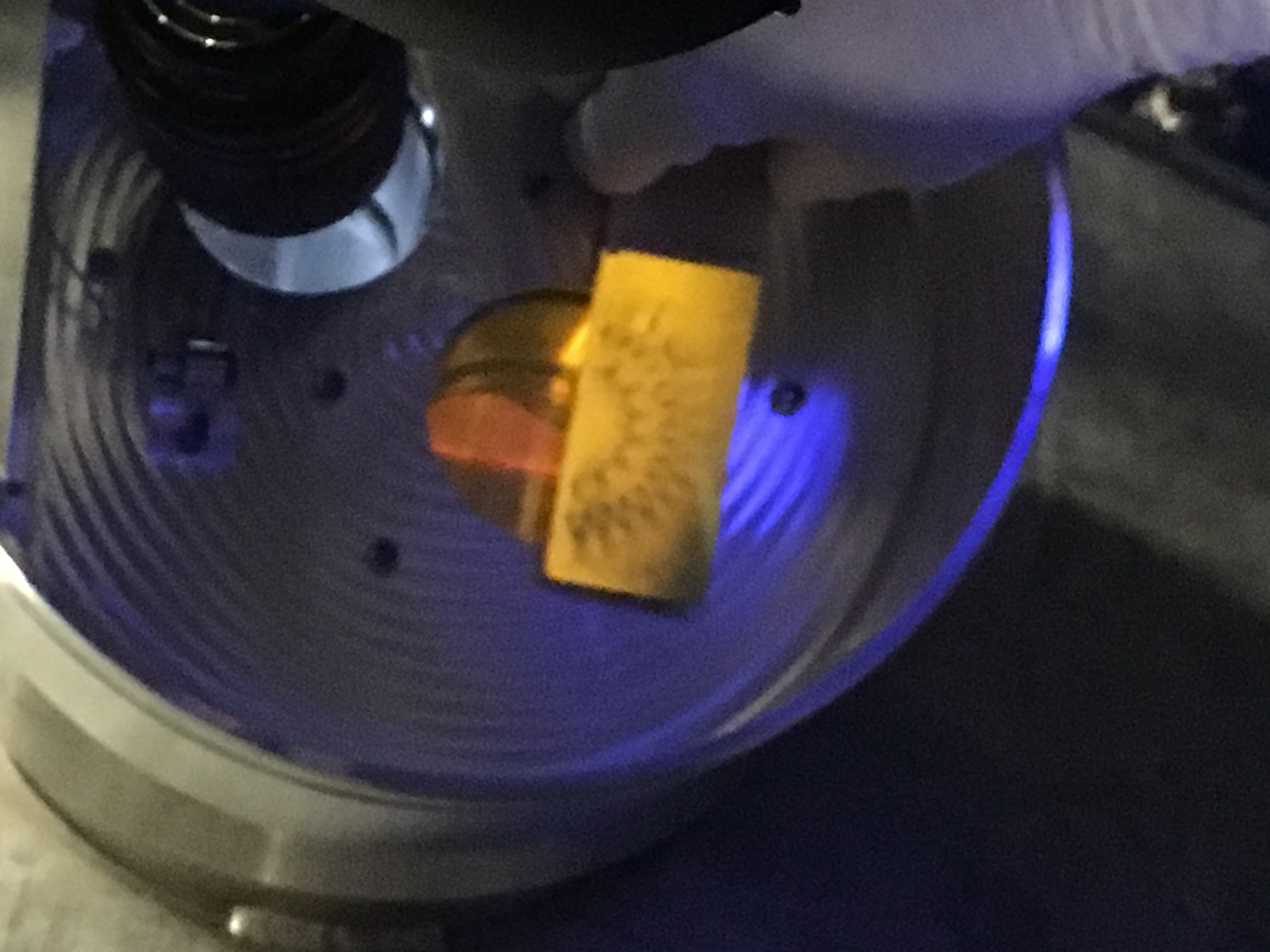
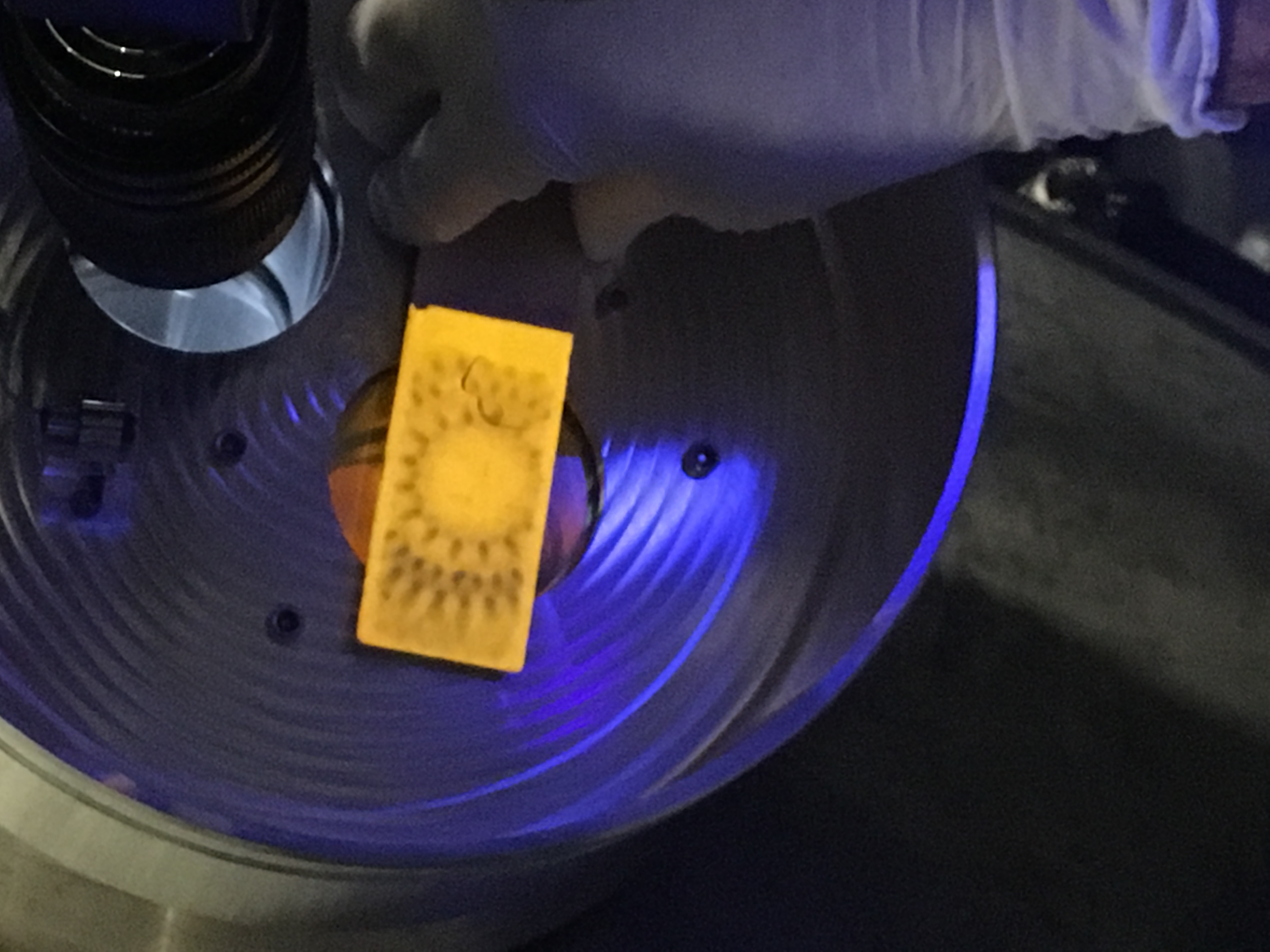
Fig 4. Central heating mask
Fig 5. Annulus heating mask top edge
Fig 6. Annulus heating mask bottom edge
Fig 7. Annulus heating mask central
Attached are:
- A 33min HWSY animated gif showing the turn-on transient of the TCSY CO2 central heating.
- The TCSY FLIR image of the heating beam.
A word to the orientation of these images: the HWSY images have global Y+ as horizontal axis, and global z+ as vertical axis. On the FLIR image horizontal and vertical are approximatrely switched (there is also a ~20deg rotation). We ought to take a reference image with a shyadow marker to clarify this relative orientation.
Note that the intensity is not completely uniform across the mask. It looks like we will still have to do a fine-tweak the beam position by about 1 cm in pitch and yaw, but that can easily be done with the top mirror picomotors. The picomotors move at about 2000cts/cm.


An iphone camera image of the ITMY compensation plate seen through the two steering mirrors and the BSC1 glass viewport next to the zinc selenide viewport.
