This morning I tried a different approach to explore the alignment of IM3/IM4 to improve PRMI buildup.
- Added slow angular lines to IM3 and IM4 OPTICALIGN filter banks:
- IM3 pitch 0.11 Hz, amplitude 500
- IM3 yaw 0.17 Hz, amplitude 500
- IM4 pitch 0.27 Hz, amplitude 500
- IM4 yaw 0.08 Hz, amplitude 500
- Collected a few minutes of data (1216572571 to 1216573394)
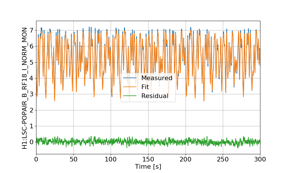
A script then reads the OPTICALIGN values and the RF18_I_NORM signal with PRMI locked. Then a quadratic form is fitted to the power fluctuations, using the IM3 and IM4 excitations as input. In other words, if X is a vector of IM3 and IM4 offsets:
X = ['H1:SUS-IM3_M1_OPTICALIGN_P_OUT16', 'H1:SUS-IM3_M1_OPTICALIGN_Y_OUT16', 'H1:SUS-IM4_M1_OPTICALIGN_P_OUT16', 'H1:SUS-IM4_M1_OPTICALIGN_Y_OUT16']
Then RF18_I_NORM is recosntructed with parameters A (4x4 matrix), B (vector of size 4) and C (scalar constant):
RF18 = X.T * A * X + B * X + C
The fit is quite good:
Then from the A and B coefficients I could compute the new IM3 and IM4 offset values that would give the largest RF18 power. The values found in this way were about 1000 cts off in picth and almost unchanged in yaw. I tried them, and found that RF18 improved a bit, but not a lot (from ~7.0 to ~7.17).
So no big improvement, but at least the method seems to work.
