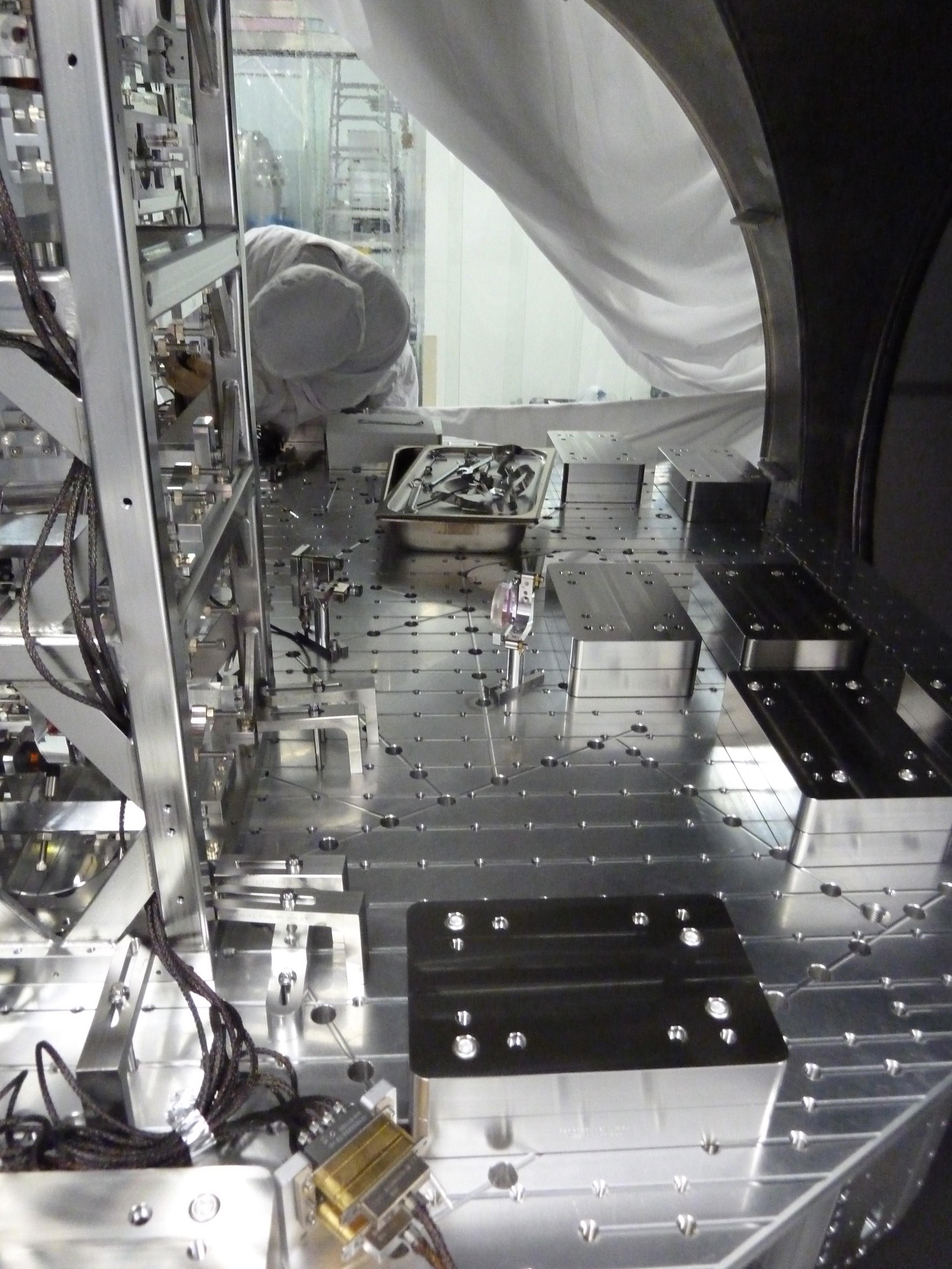
Everything we planned to install at this stage was installed.
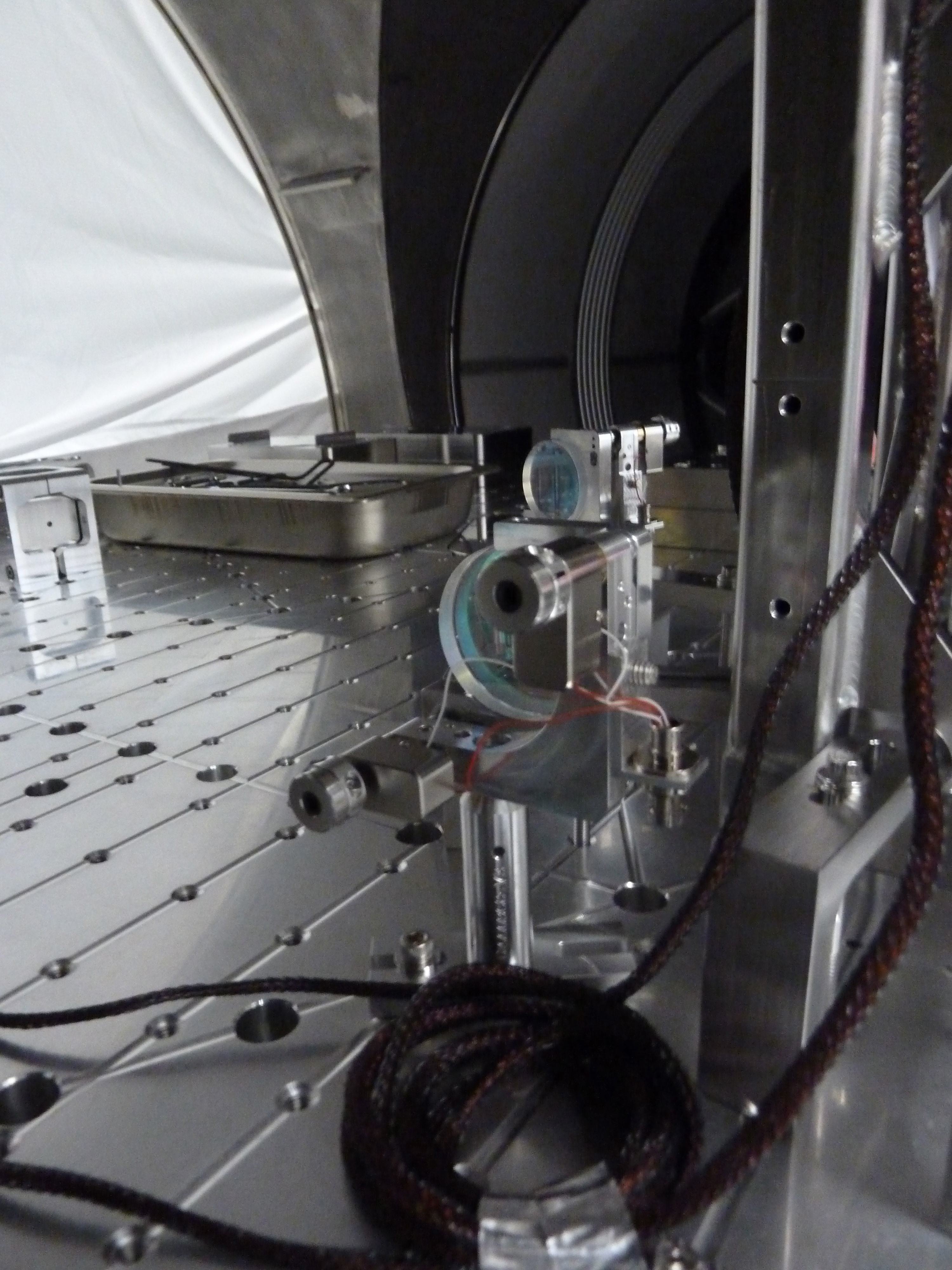
Picomotors are connected to the in-vac cable (we copied LLO cabling layout), which was connected to the connector bracket 3 upper floor in chamber, which is connected to the feed through. We connected the picomotor driver and the test interface to the feed through from outside, and all picomotor worked:
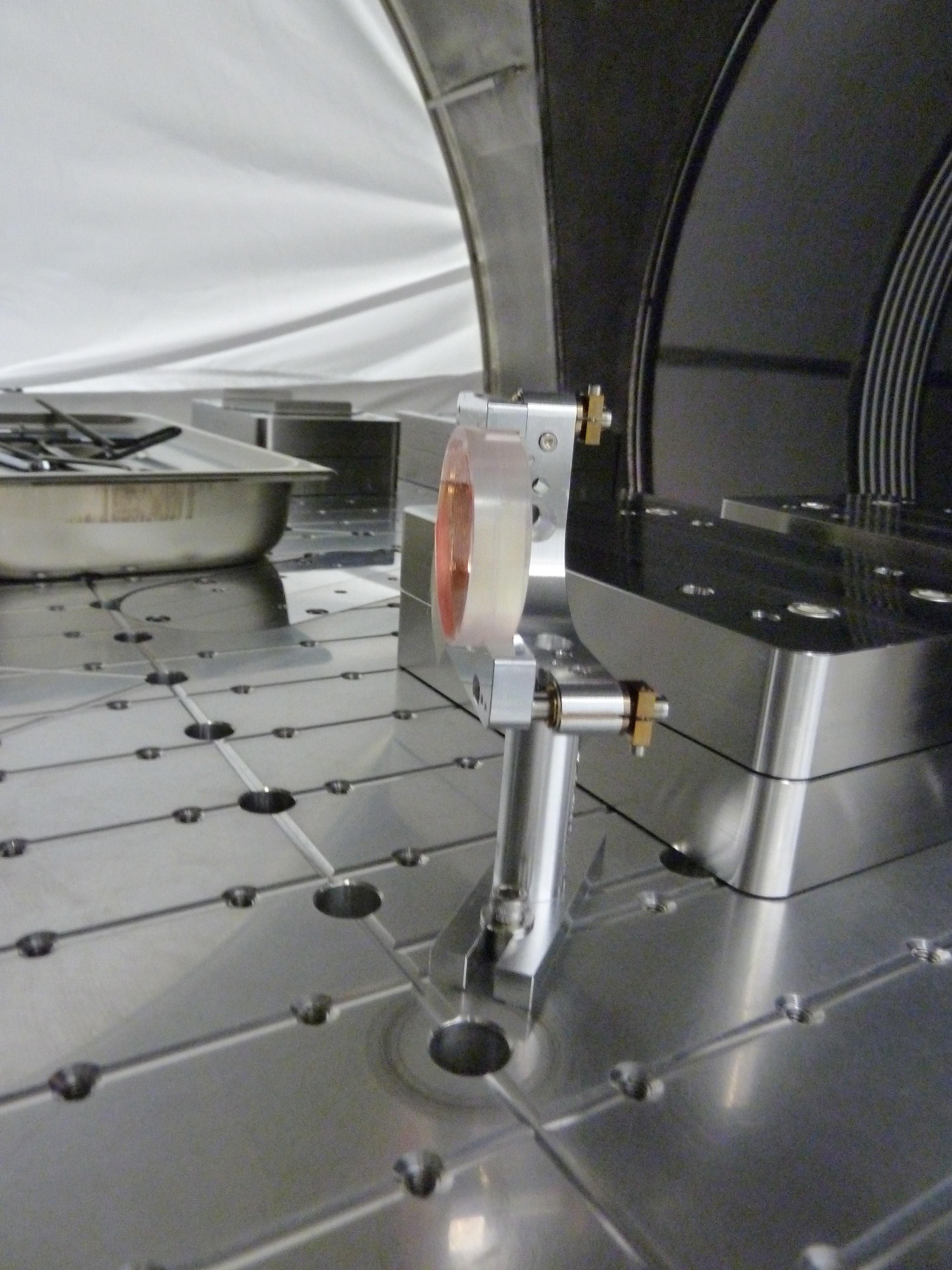
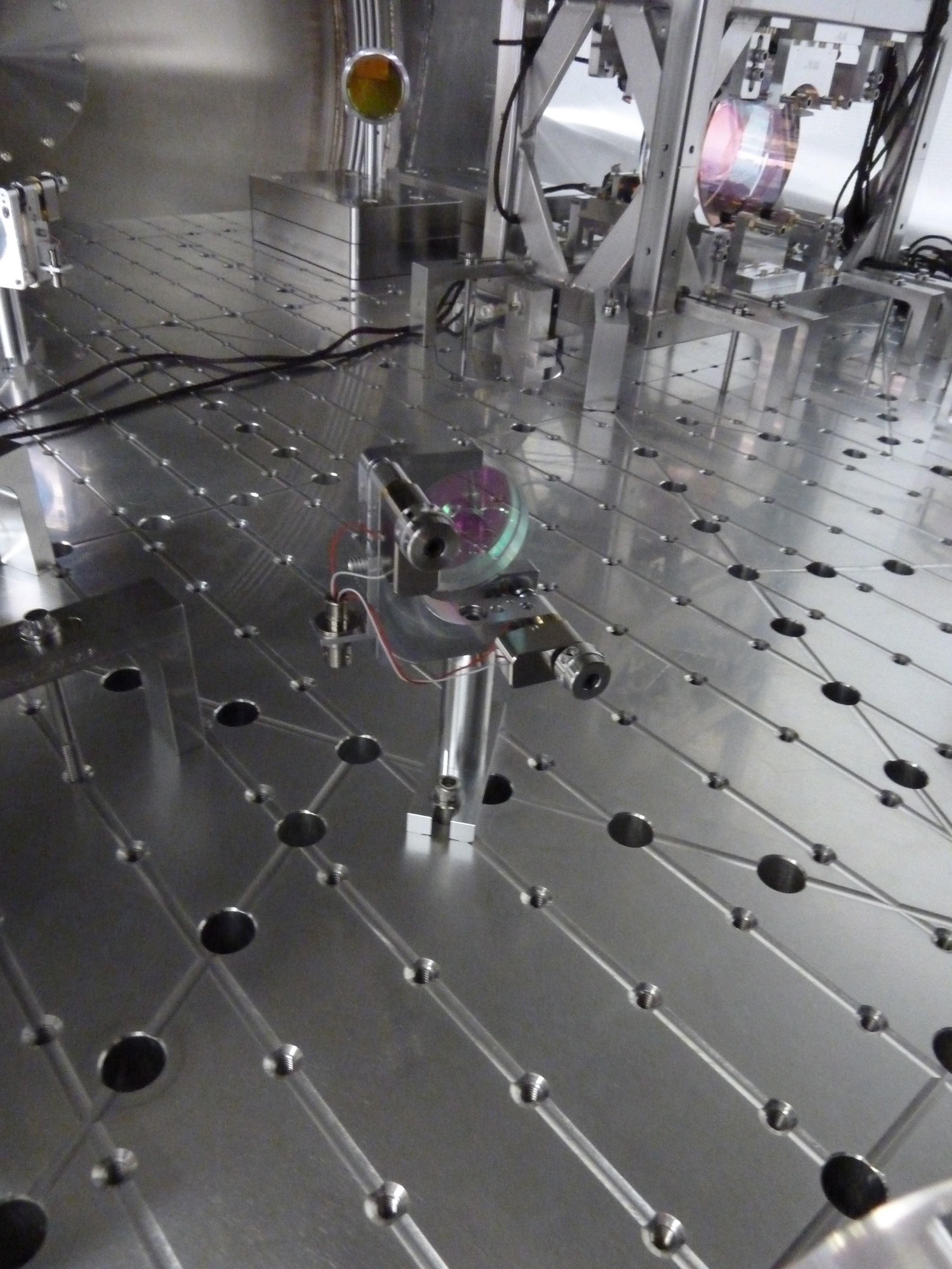
Pico 1 = ISC steering mirror just upstream of QPD sled.
Pico 2 = ISC steering mirror further upstream of QPD sled.
Pico 3 = IO steering mirror for IO QPD.
Pico 4 = ISC steering mirror that directs POP to HAM1.
We used a laser pointer and a hand held LCD QPD readout box to check the QPDs. Though it cannot test the output of individual quadrants, and though the laser pointer beam was too big (or, rather, QPDs were too small) to put the entire beam on one quadrant, both IO QPD and ISC QPDs seem to respond to the light reasonably.
Some IO components (e.g. IO black glasses and beam dumps and such) will be installed later.