[Aidan, Danny, TJ]
Summary
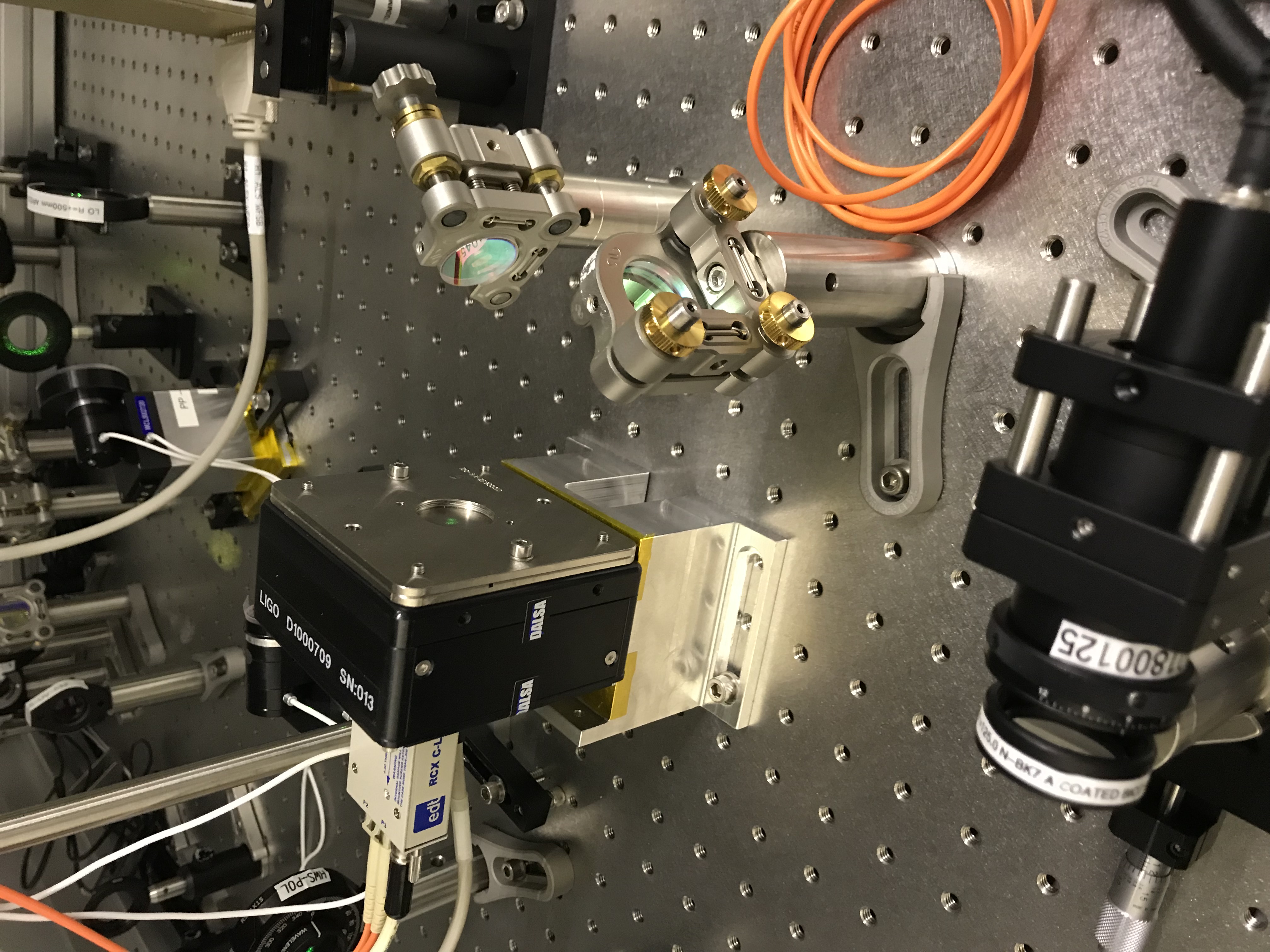
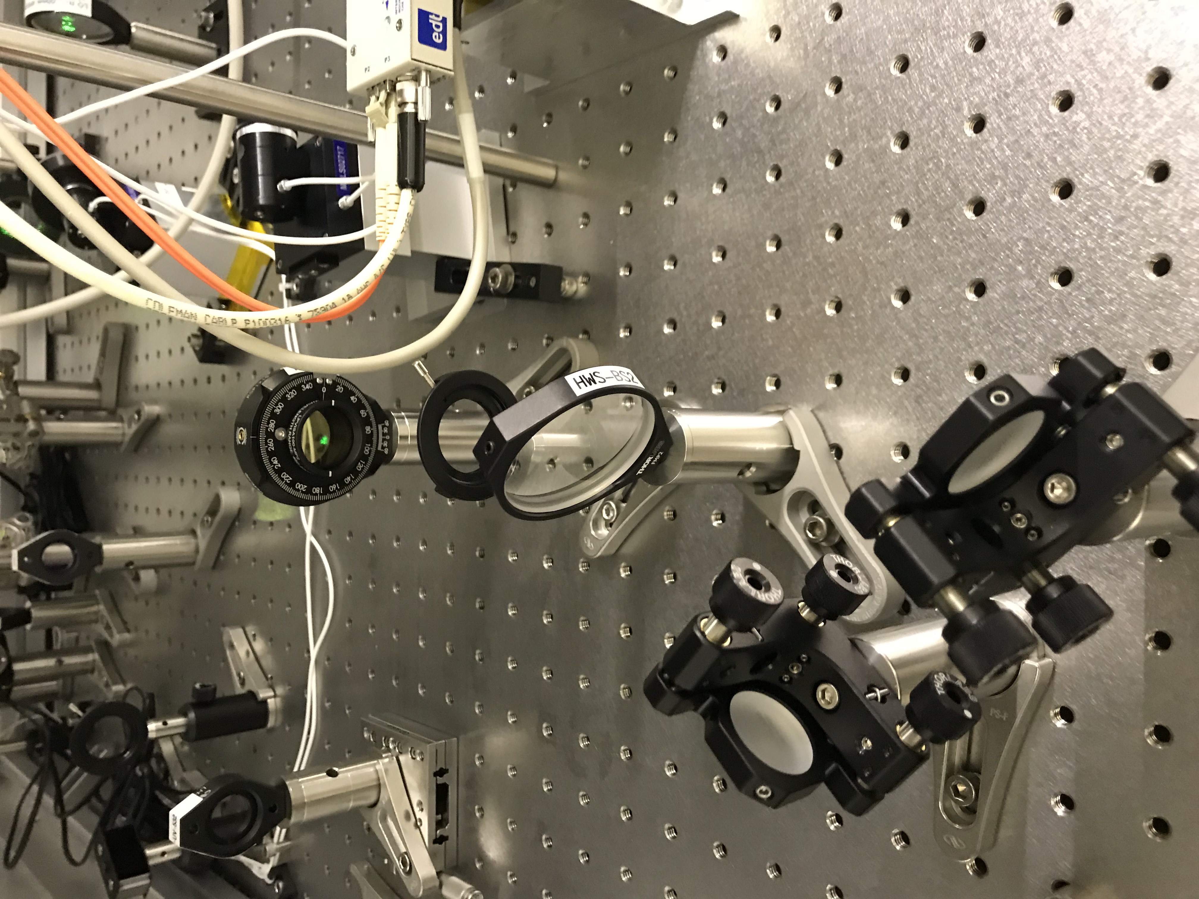
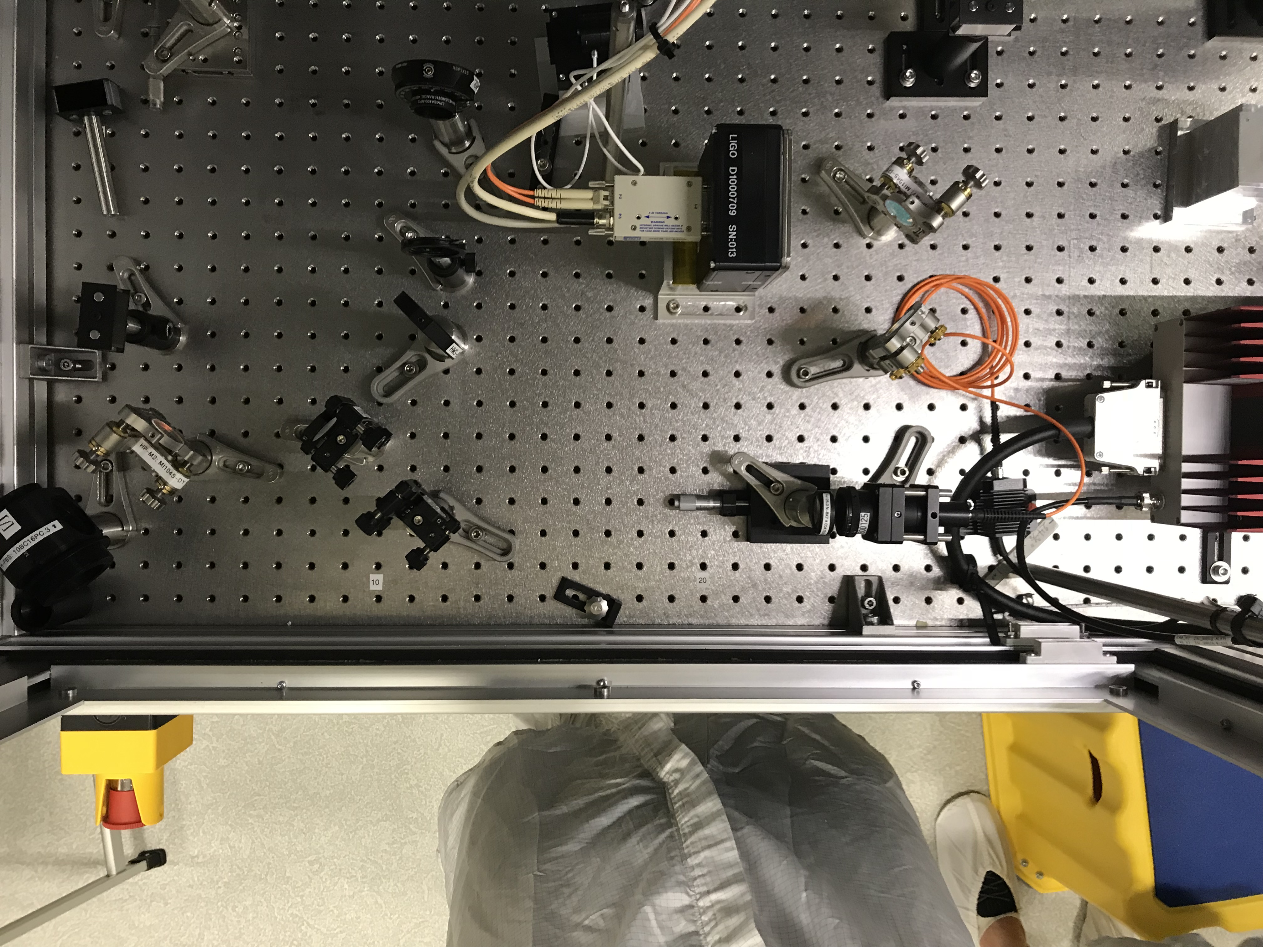
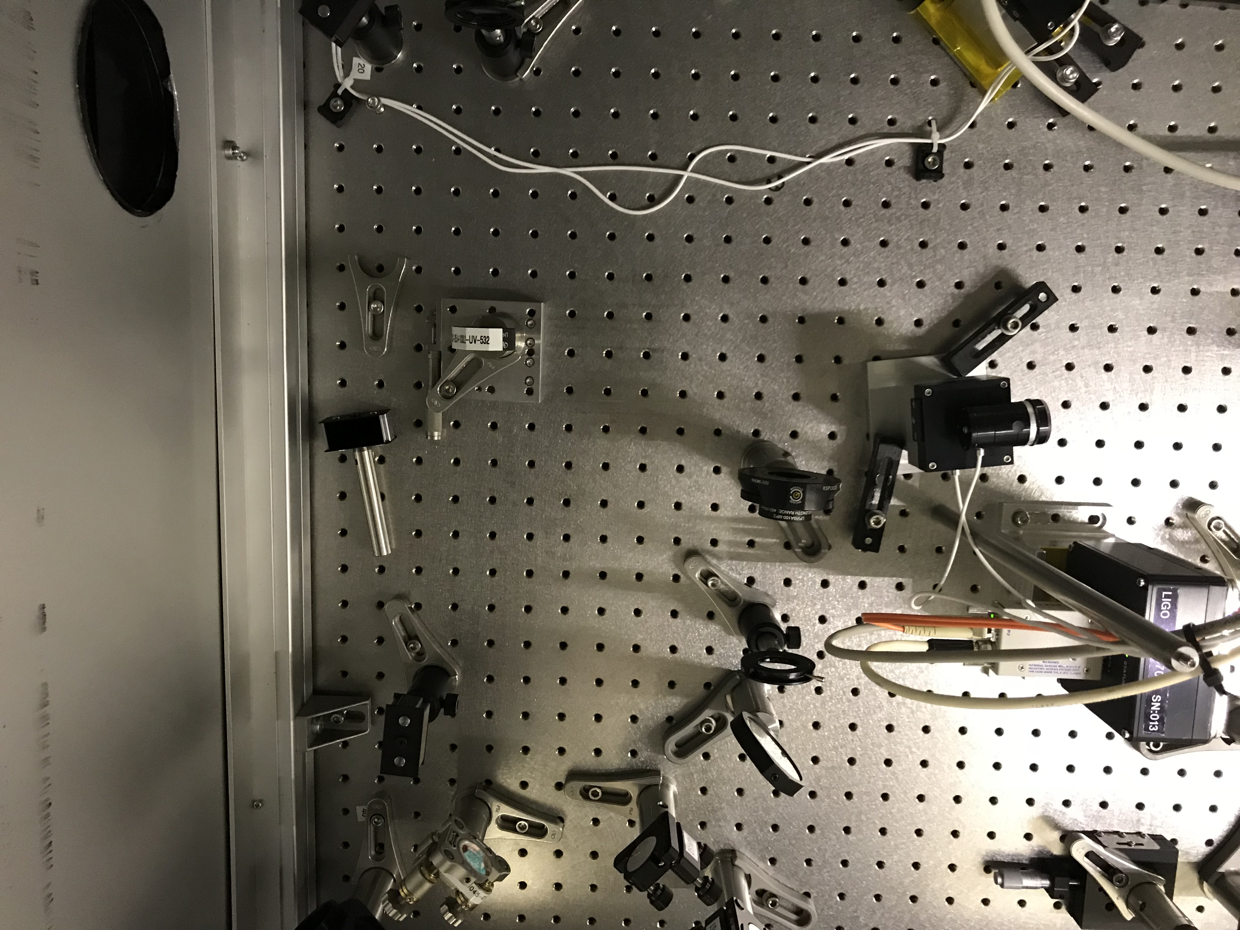
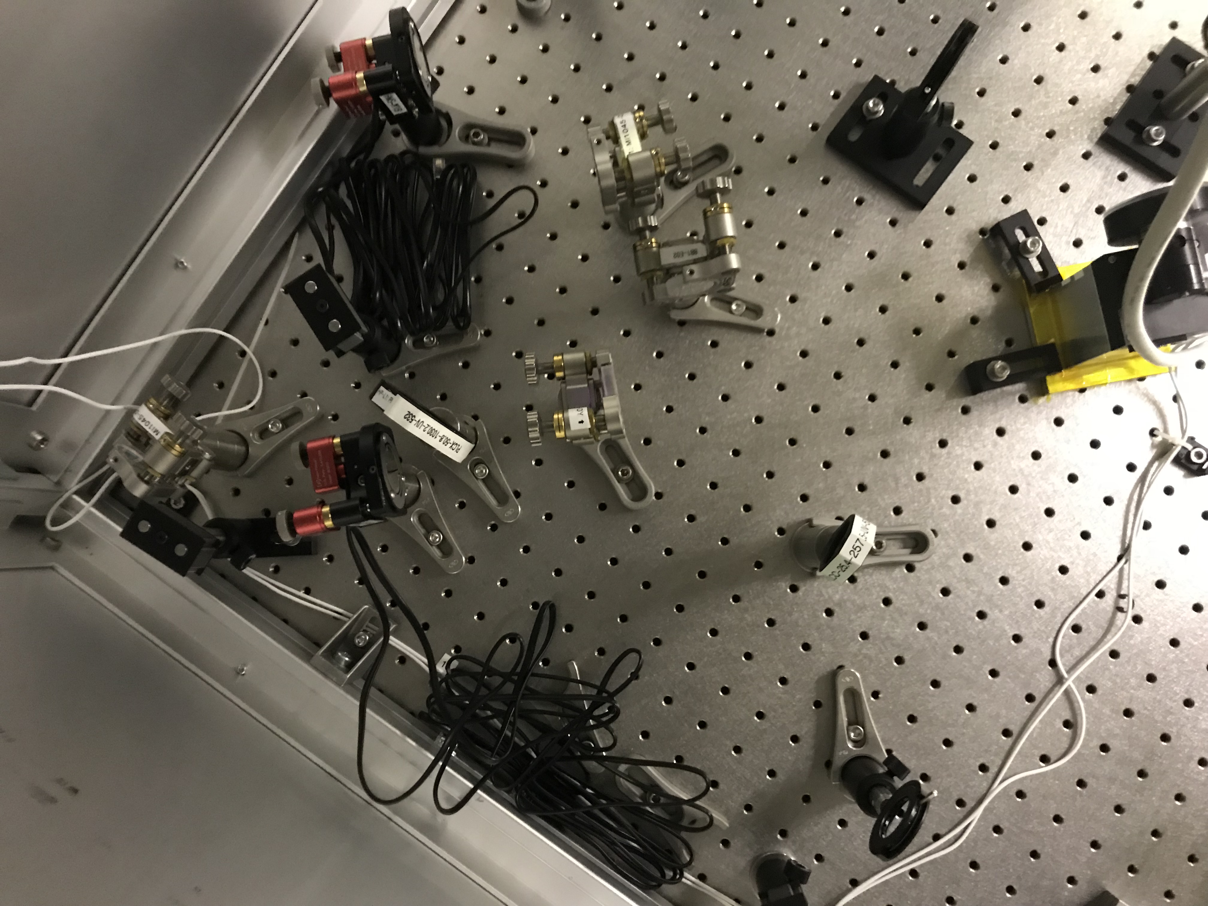
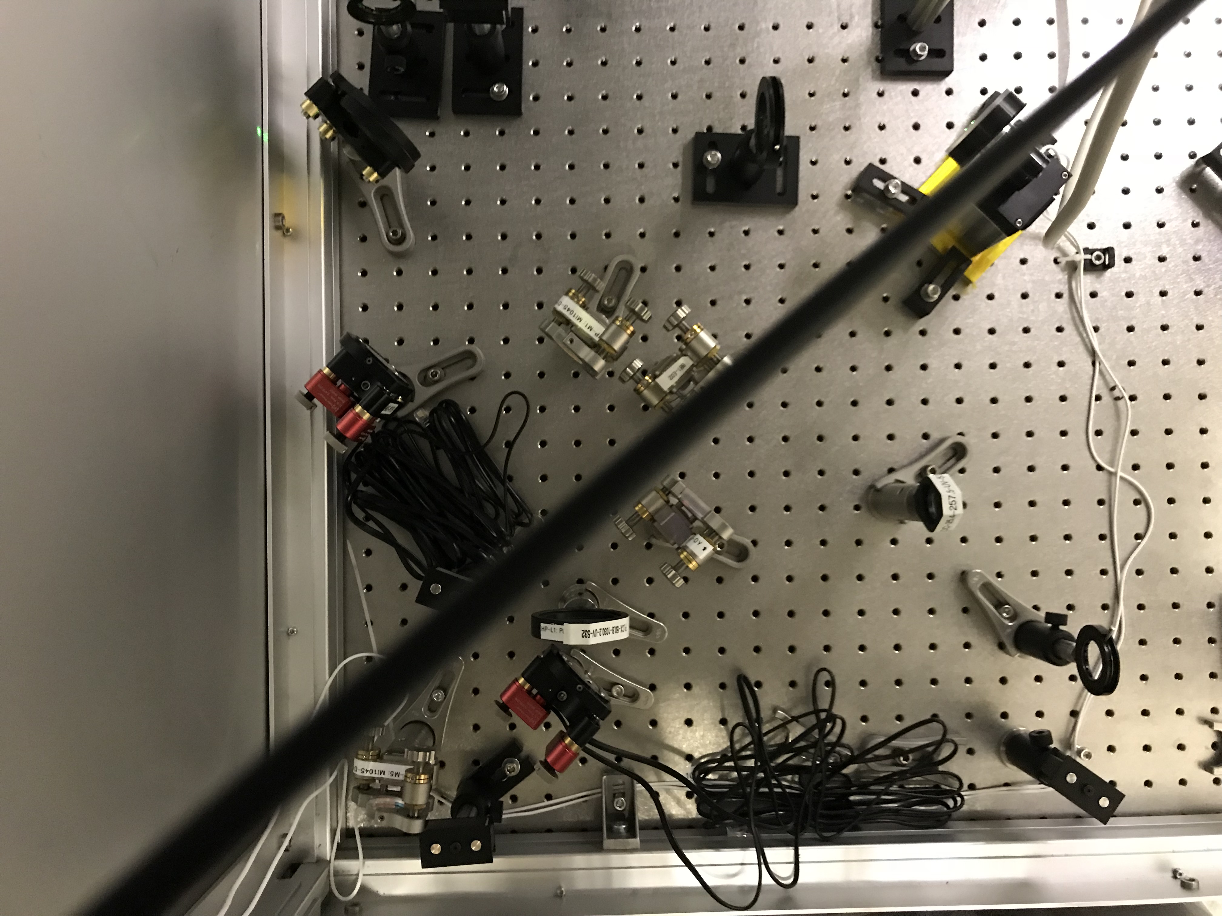
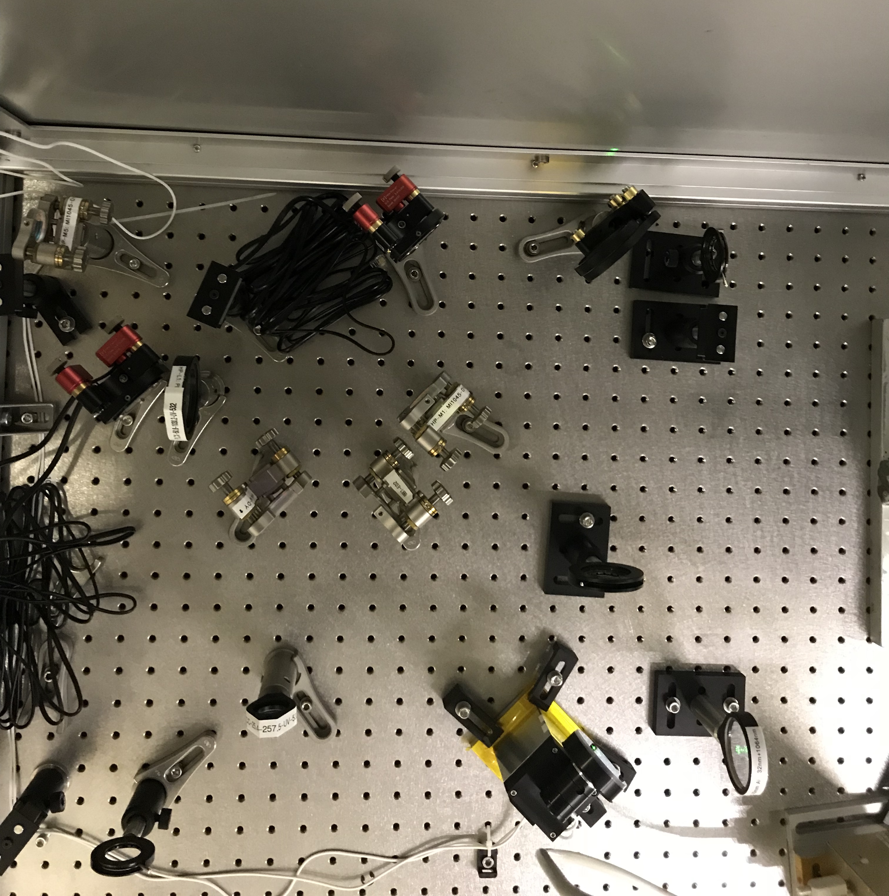
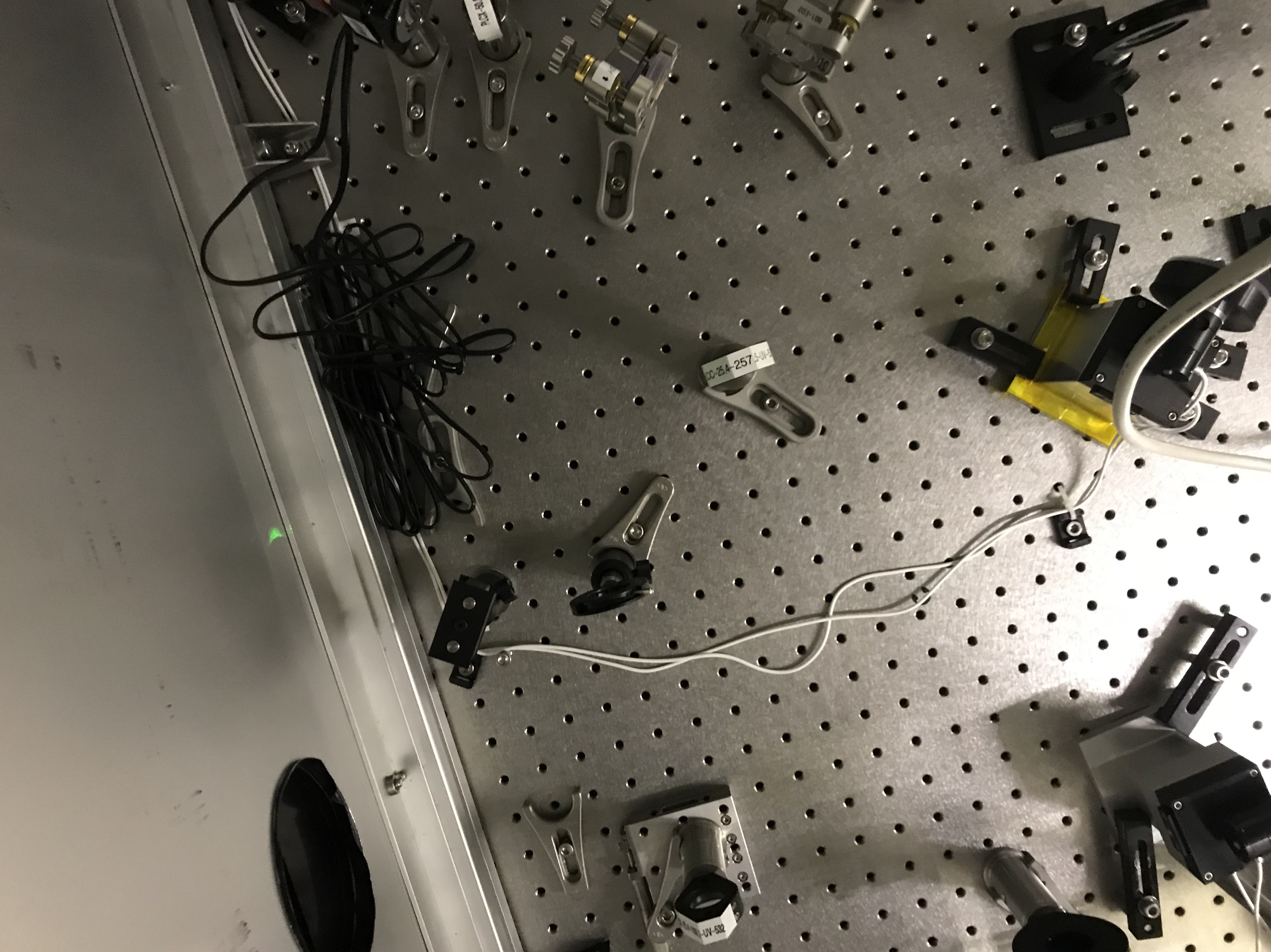
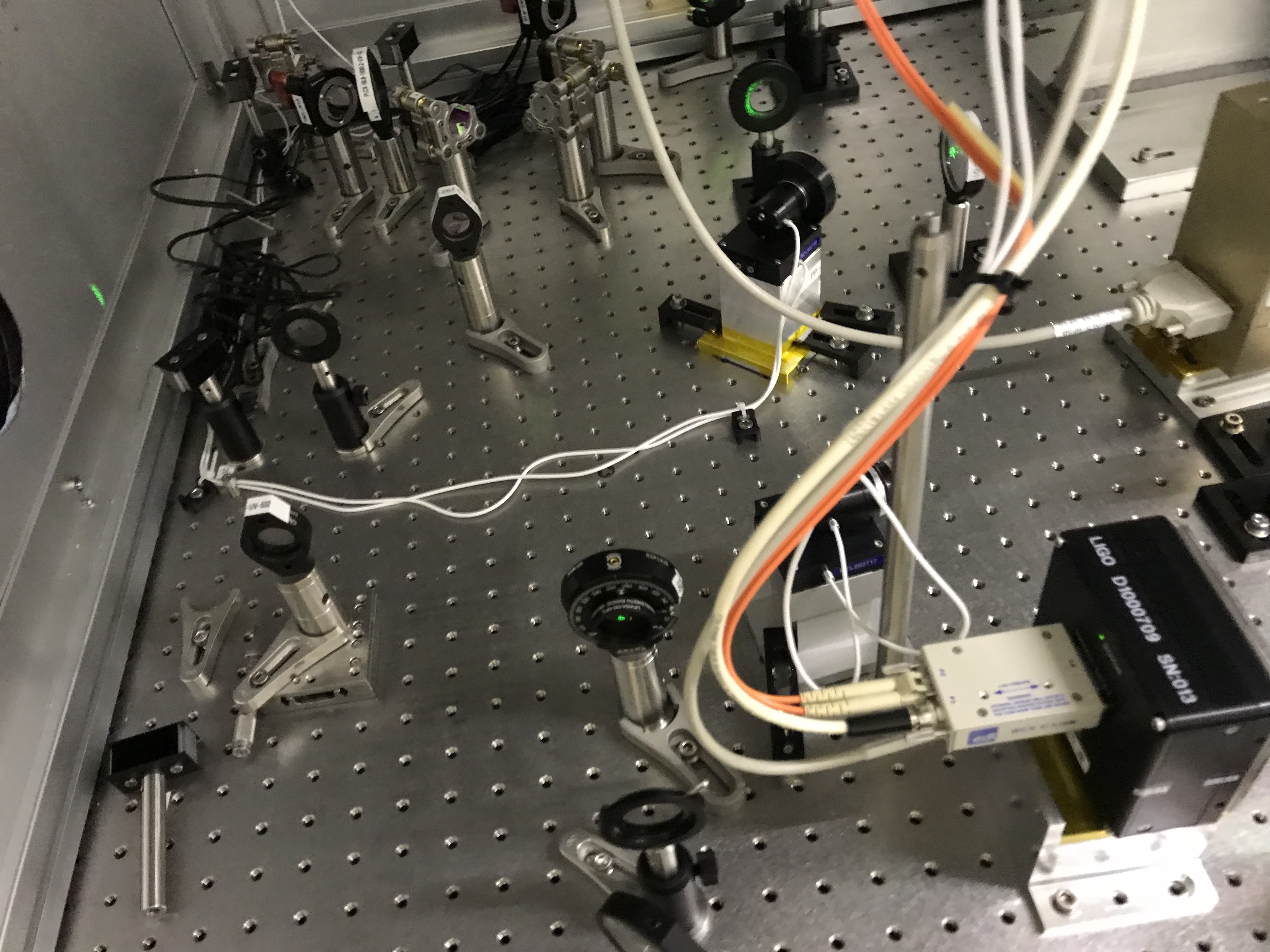
We finished setting up the ETMX HWS. The alignment may have been bumped in the final steps as the HWS spot pattern envelope is smaller than the intensity distribution. ALS leaks onto the HWS camera. Photos of the layout are attached.
Alignment
We finished aligning the HWS source beam to the ETM on HWSX. Once again, we could see what looked like the AERM aperture.
We adjusted the picomotors (manually) to optimize the alignment of the intensity pattern to the shadow of the AERM aperture. We struggled to get the intensity moved up in pitch - it remained a little low relative to the aperture but horizontally it looked centered.
When we closed the iris on the fiber launcher (that is nominally centered on the intensity distribution), it was centered close to the center of the AERM shadow.
We readjusted the lens position after the fiber launcher so that the beam was focussed approximately 1.3m along the optical axis (around the location of the first lens on the outgoing beam).
We tried the ETM pitch modulation technique to optimize the imaging but the results were inconclusive due to non-linear fluctuations in the Y-centroid signal on the HWS camera. We estimate that the conjugate plane of the HWS is within 50m of the ETM (or the HWS is within 10cm of the conjugate plane of the ETM). One option for improving this is to simply try to get the AERM aperture as sharp as possible but moving the HWS along the optical axis.
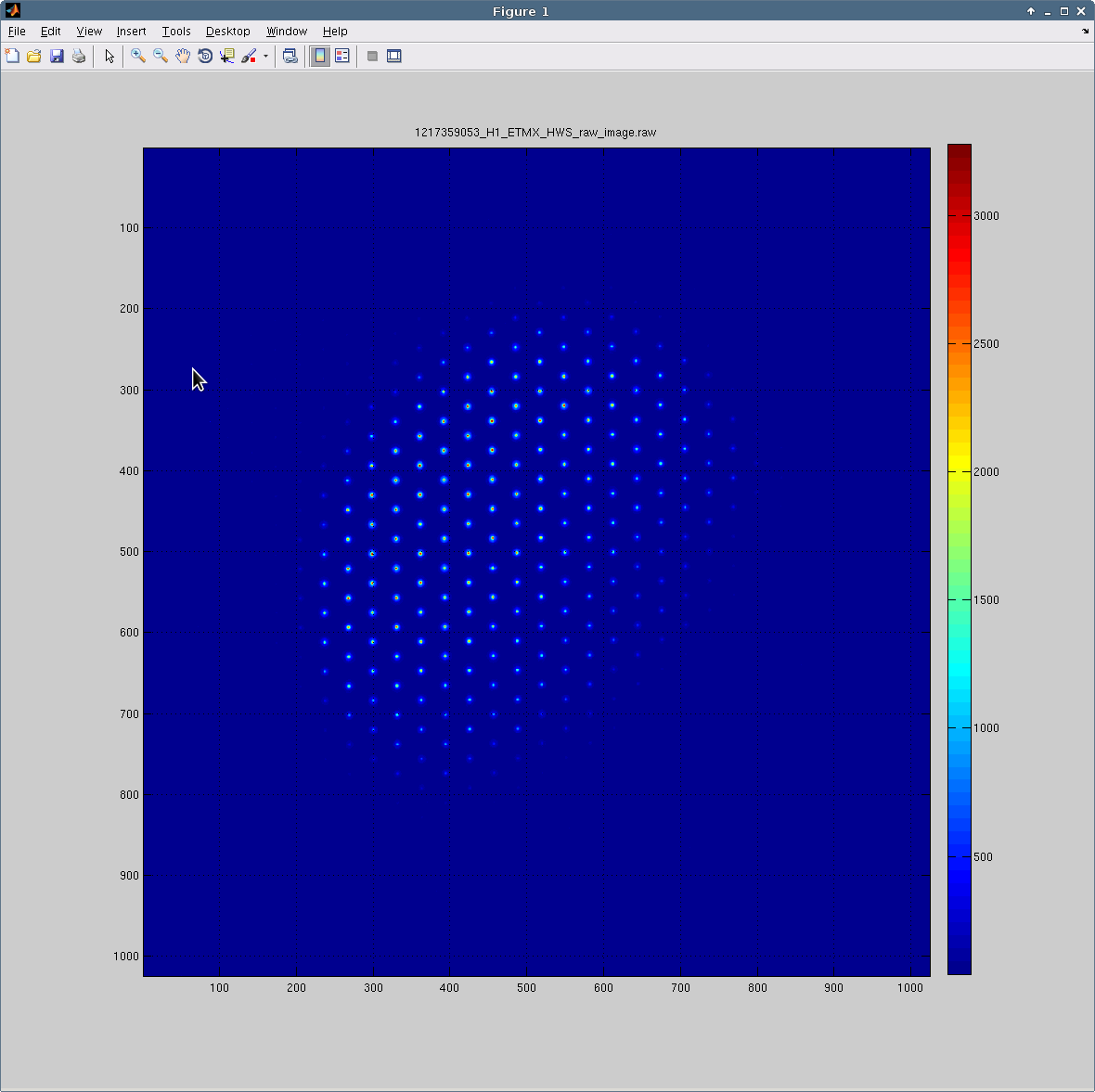
We installed the Hartmann plate on the sensor and started the HWS software. Closer inspection of the HWS pattern shows that the lower right section (in the attached images) has disappeared. It's possible that we might have clipped the beam somewhere in the final steps of installing the plate. We should remove the plate and re-check the alignment.
Optical layout (distances between optics)
| Optics | Distance |
| M1A to M1B | 118 mm |
| M1B to L1 (lens) | 118 mm |
| Lens to M1 | 28 mm |
| M1 to L2 (lens) | 498 mm |
| L2 (lens) to M3 | 314 mm |
| M3 to BS2 (now a mirror) | 98 mm |
| BS2 to L3 (lens) | 585 mm |
| L3 (lens) to M3 | 148 mm |
| M3 to M4 | 65 mm |
| M4 to HWS-BS | 656 mm |
| HWS-BS to M6 | 324 mm |
| M6 to M7 | 80 mm |
| M7 to HWS | 86 mm |
| HWS-BS (front) to MS1 | 130 mm |
| MS1 to L_fiber | 265 mm |
| HWS-BS (front) to POL | 145 mm |
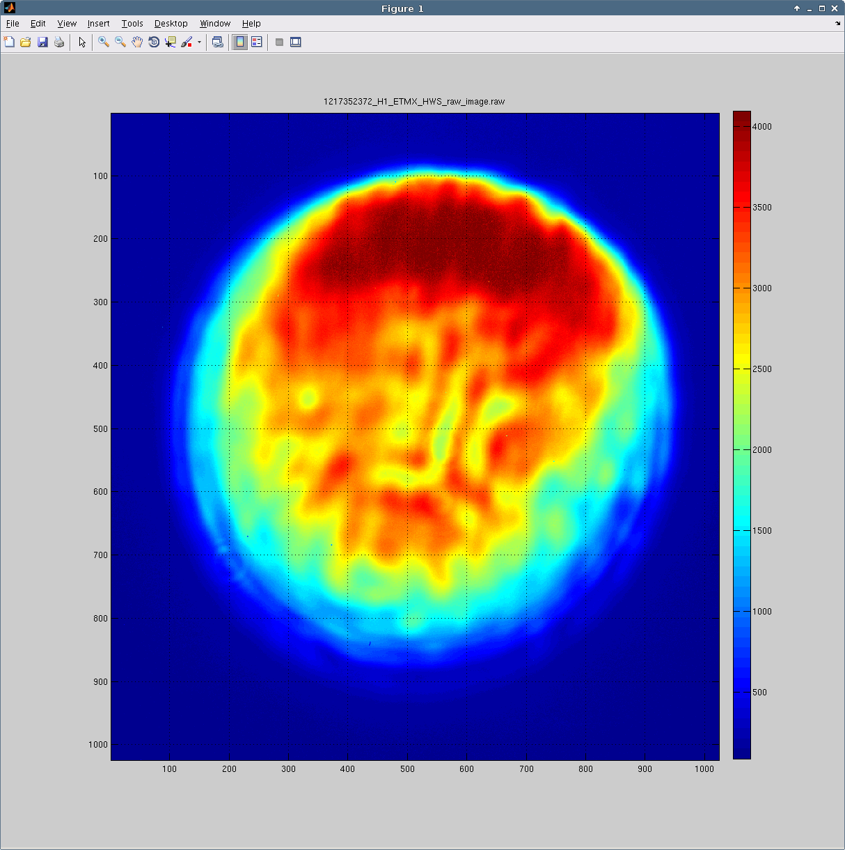
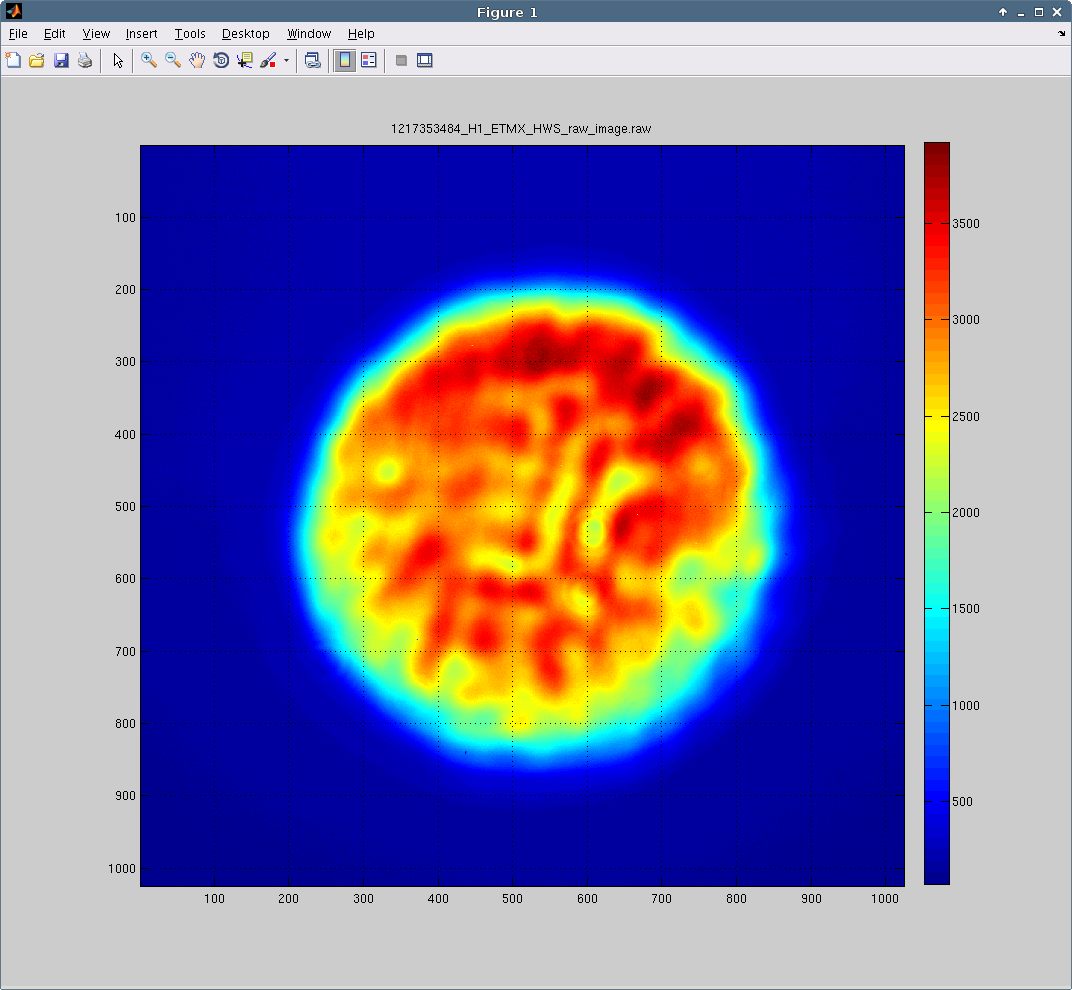
HWS return beam images
Fiber launcher Iris open
Fiber launcher iris partially closed
Hartmann sensor spots
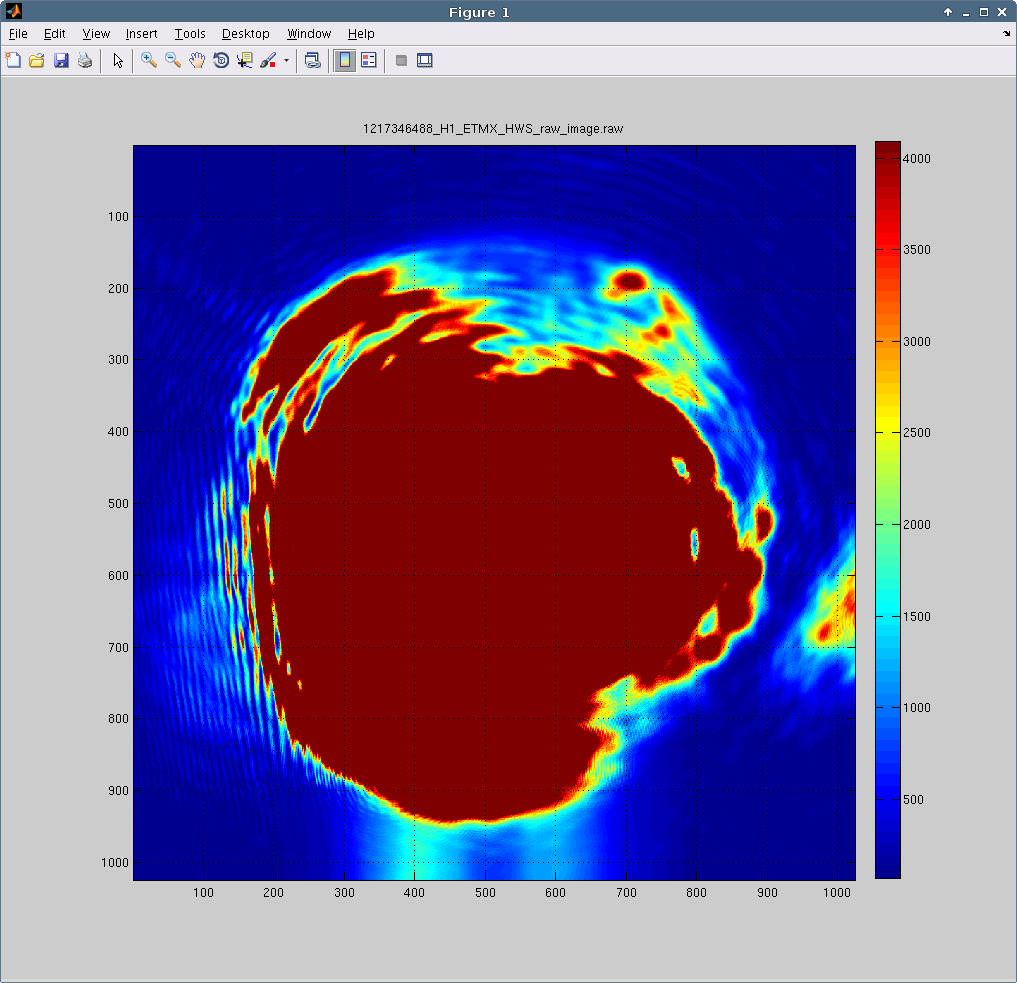
ALS leakage onto HWS camera
The ALS beam leaks onto the HWS camera as shown in the attached image. Like the ETMY ALS beam there is probably some small polarization rotation inside the vacuum system.
Spherical power measurement
The initial spherical power (over approximately 5000s) shows very low noise (perhaps 3uD - 6uD RMS). The ALS laser was unshuttered at the end of this time and saturated the camera.
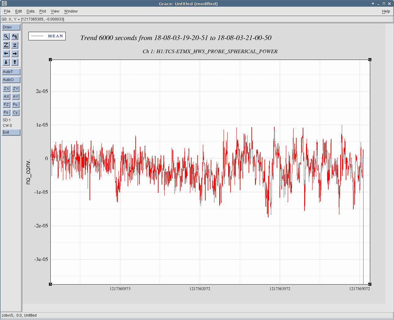
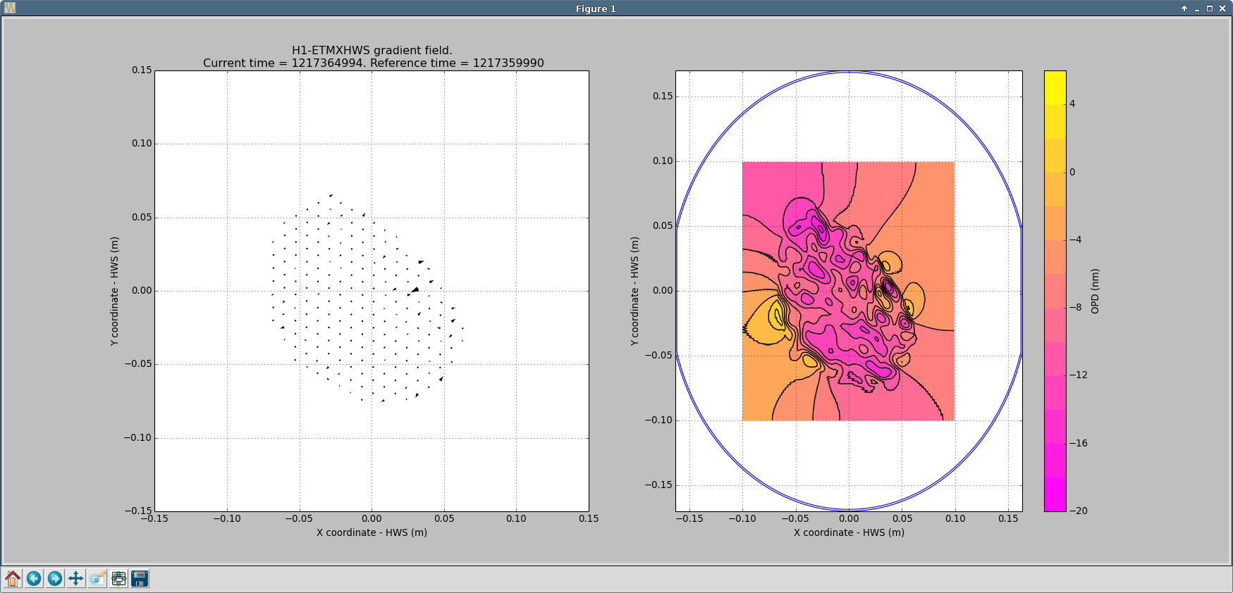
Here's a contour plot from after we stopped messing with the alignment and before commissioners started using ALS again. It looks pretty flat, which is a good sign. Ring heater tests will tell us more.
The layout is shown in https://dcc.ligo.org/LIGO-D1201448