Jenne, Gabriele, Hang
We are able to close all the DRMI ASC loops except for the SRC2 (AS_C DC-> SR2; as we have not pico'ed AS_C yet), with the arms held off-resonance with the ALS beam.
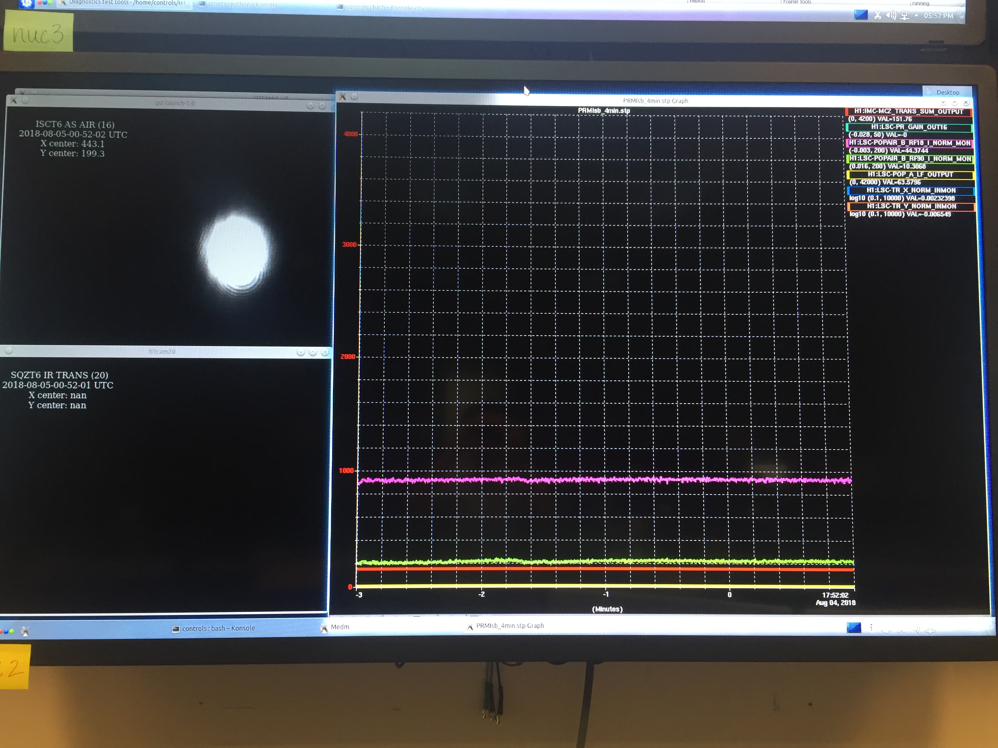
See the attached photo. The AS port beam seems round. The POP buildups seem to be stable, with LSC-POPAIR_B_RF18_I_NORM = 44 and LSC-POPAIR_B_RF90_I_NORM_MON = 10. As a comparison, the sidebands' buildup in PRC last night (without active ASC) were POP_18 = 38 and POP_90 = 11. The lock is also stable for hours with the loops on
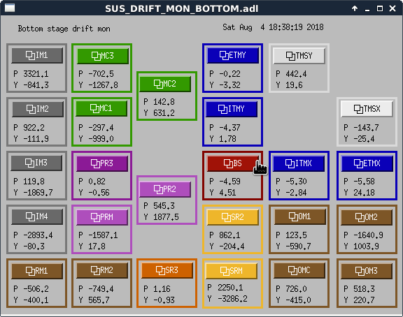
The osem values are also attached.
The settings used to close those loops are put into the ISC_DRMI guardian. However, we cannot directly request the 'ENGAGE_DRMI_ASC' state right now. This is because to stay locked, when we move PR2 we need to compensate the PRC axis with PRM, thus we should turn on those two loops together. However, somehow in the guardian setting the PRM M1 stage seemed to be deliberately disabled (why?), and pushing only on PRM M3 will lead to saturation. So far I have to walk PRM-PR2 to close to their locking point, and then engage the loops from there. Also it seems weird that the PRM alignment giving us the best PRX buildup in the initial alignment (which is also the alignment to allow us to easily grab the DRMI lock) appears to be very different from the one giving best DRMI buildups when all loops are closed...
For the lock acquisition sequence, once the DRMI ASC loops are closed, transition to 3f seems fine, but lockloss kept happening at the 'OFFLOAD_DRMI_ASC' stage.
==================================================================
Details:
1. Input axis (IM4 + PR2):
We sense the input axis (IM4 + PR2) using a combination of REFL_A_9_I and REFL_B_9_I WFS. Here we have phased the longitudinal PDH signal into the I-phase of each quadrant. We measure the DC responses of the error signals and then invert it to get the following sensing matrix:
| REFL_A_9_I_ | REFL_B_9_I | (for pitch) |
| 1.0 | -1.6 | INP1 (IM4) |
| 1.0 | 1.0 |
PRC2 (PR2) |
| REFL_A_9_I_ | REFL_B_9_I | (for yaw) |
| 1.0 | -1.3 | INP1 (IM4) |
| 1.0 | 1.0 | PRC2 (PR2) |
2. PRC axis (PRM):
Once we closed the INP1 and PRC2 loops, we walked the PRM alignment to optimize the POP_18 buildup. The best buildup we found corresponds to a beam position on the ASC QPD (ASC-POP_A_PIT) was PIT ~ 0.85 and YAW ~ -0.1 (normalized by the sum). We then put offsets (-0.85 in pitch, 0.1 in yaw) to zero the QPD's DC output and feed the residual signal back to PRM.
As a reference, the old offsets were PIT = -0.6 and YAW = 0.216. The old pitch was set on June 22, 2018.
3. SR2:
We noticed that the beam was clipping on OFI in yaw.
We measured in the single bounce configuration (misaligning PRM, ITMY, ETMX, and SRM) the AS_A_NSUM, with the AS DC centering loops engaged. The edge values for yaw (in SR2 slide bar units) were from 75 to 360. Our old SR2 yaw was parked at 370. To avoid clipping we moved the it to a slide bar value of 300 in yaw. The pitch seems to be fine. We have not yet pico'ed AS_C so the SR2 is not yet actively controlled.
4. BS & SRM with AS72:
The BS and SRM are actively controlled with the new AS72 scheme. We first optimized the BS/SRM alignment as much as possible by hand, and then phased AS72 WFS such that the DC power showed up in the I-phase. By doing so we the Q-phase should be free from contamination due to errors in spot centering (recall that the AS72/AS36 is similar to an oplev signal, or a 2f signal, with non-vanishing spot at 72 MHz/36 MHz; this is different from a regular WFS using the 1f PDH signal where spot vanishes at RF if the cavity is locked without offsets).
The sensing matrix we use are (the ratios were set to decoupling the BS/SRM, the overall scale to match the old AS36 response)
| AS_A_72_Q | AS_B_72_Q | (for pitch) |
| 300 | 1500 | MICH (BS) |
| -300 | 600 | SRC1 (SRM) |
| AS_A_72_Q | AS_B_72_Q | (for yaw) |
| 75 | 500 | MICH (BS) |
| -200 | 140 | SRC1 (SRM) |
Note that we are able to use only the Q-phase signals here.
Previously (LHO:42809) we could not do so presumably due to clipping or unintentionally left on CO2 central heating (previously the contrast defect measured in simple MICH was as high as 2%; now without any heat the contrast is ~0.2% or so in power).
==================================================================
TO DO:
0. Enable PRM M1 stage. (Why was it commented out in the previous guardian setting?)
1. Balancing the gains of each AS72 WFS quadrants. This can be done by offseting SRCL and then drive SRM in length. This should lead to a AM signal which can be seen at each quadrant's I phase.
2. Try AS72_I as the centering signal at the AS port. This might be more immune to junk lights at DC.
3. Measure the 118 MHz mod depth. E.g. from AS72 sum / AS36 sum.
4. Tune the loop shapes, especially the MICH loop. Due to the low AS72 mod depth ~ 10 mrad, if we use the current loop shape (roll-off starts at 20 Hz) the shot noise limited MICH ASC noise would be high enough to show in DARM. Need to move the roll-off to lower freq.
==================================================================
Aside.
It seemed that the spot position in the XARM does not match the green camera's setting (LHO:43112) any more. For this report's alignment (also similar to yesterday's osem values), the camera image is 100 cts too high in pitch in ALS-X_CAM_ITM_PIT_DIFF. If we turn the ALS DOF3 on in the initial alignment, the IR beam no more flashes in the XARM. We might want to either update the camera's locking point, or manually turn off the DOF3 alignment servo for XARM during initial alignment. Alternatively we can walk the corner alignment to the old camera's setting (science the current beam was a bit too high on ASC POP A QPD).
It seems like the PRM M1 offloading was only commented out in July this year, so I've added it back in.
One potential explanation for the problem with the OFFLOAD DRMI state was that it turns off the MICH ASC loops and re-engages it with AS36 in the input matrix. We used to use AS45 for BS control while the arms were off resonance, which was more reliable than 36 when the starting alignment wasn't good, and in this state we would switch the input matrix to 36 before starting the CARM offset reduction. I've commented this out for now.
We did use this ASC state once this afternoon, and it improved our alignment very nicely. The other times we tried it the transient while engaging the loops unlocked DRMI.