WP 7749 (Add GS13INF..._OUT to Frames) FRS 11049 (HAM2 & 3 GS13 Gain Switching failure)
I've only looked at the first switch failure closely but I have many more in the can (just ask the operator JeffB) now with the model change adding the GS13INF_.._OUT channels to the frames.
My theory at the moment looking at the first trip is that the corner 2 & corner 3 switching is cross wired. I don't know where yet as that mapping is complex--working on it. Meanwhile...
Look at the attachment and listen to my story...
After getting the GS13INF_OUTs into the frame, I put the platforms into nominal ISOLATED state except the GS13s were in the low gain mode. I manually toggled off every filter for the GS13 gain state and noted the success of the switch. For HAM4, every filter switched with out bothering the platform. On HAMs 2 & 3, corner 1 H & V all switched with out bothering the platform. Conversely, on HAMs 2 & 3, corners 2 & 3 both H & V, every switch of FM 4 or 5 tripped the platform. I did not repeat every switch because the trips took time to recover, and, trips of the verticals on the ISI also tripped the SUSs on board. However, every repeat yielded the same result as noted, there was no inconsistent result. So I zoom into the first trip when I toggled the DW filter on HAM2 H2:
1/2 second of data displayed. Note the H2 (corner 2) SWSTAT change as the FM5 Dewhitening filter changes state. So you can see that the H2 signal (upper left green) gets more high frequency noise even compared to before the switch when the analog whitening is on and its digital DW filter is on; so the digital DW goes away but the analog whitening is still on. Conversely, looking at the H3 GS13 signal (lower right,) the analog & digital whitening and dewhitening filters are on and then the analog whitening is disabled and the digital dewhitening remains on and the signal gets very clean. Note that the H1 GS13 signal is unaffected.
So, bottom line, current theory: corner 2 digital filter is wired to corner 3 analog filter.
Why it could be happening. Maybe best bet is the problem where long long ago, the PSL group asks SEI/ISI to change feedthrus on the chamber because cables they had would not reach the flange. Normally on the ISI, corners 1 & 2 are near each other because the first CPS satellite crate has room for two corners ( there is not a separate crate for each corner on the HAMs.) When SEI changed to a different chamber feedthru, ISI cable length limits necessitated putting corners 1 & 3 into the same CPS satellite crate. We wanted all a corner's channels to go to the same feedthru so GS13 and coil drivers cables were also moved (see SEISMIC REFERENCE note on D1002873.) Since the CPS channels from a crate are on the same cable, corners 1 & 3 go into the same Interface chassis and hence the model must reflect this difference. It is around here that I suspect the problem.
The python command scripts must manage to most of the time switch the corners 2 & 3 quickly enough that it seems to work, usually. The guardian scripts however must do it just enough more slowly that it blows up.
I'll look at the other switches done and see if this story all holds up.

I hope this is the problem.
This can be easily checked by manually switching just one filter at a time.
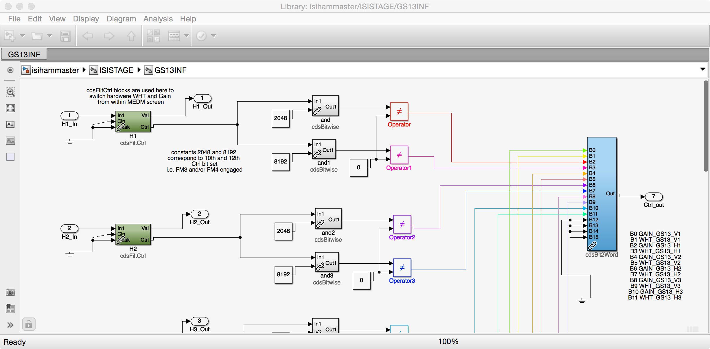
Switching the Gain or Whitening filters from the GS13_INF filters can be done manually. The engagement of the filter module is the event which switches the digital BIO. I've attached a bit of the GS13INF module from the HAM control diagram to show this.
Thanks Brian--Yes, switching the filters manually is how I tested this: " I manually toggled off every filter for the GS13 gain [& whitening] state and noted the success of the switch."
I'm not sure if the BIO readback is helpful tho as if the model & hardware are cross-wired, the medms will suggest a correct switch. There might be some monitor on the BIO chassis we could pick off otherwise a thorough comb through the model and wiring is in order.
Herein however is the second instance that I again state is very good indication of the miss-wiredness: Attached is ~1/2 second of full data where now the digital gain (FM4) is turned off on the corner 2 horizontal GS13 and we see the H3 output blow up while the H2 signal goes quiet w/o its compensating analog gain. Least one be wary about the signals being fouled by the platform trip, look at the H1 signal where there is a clear gap between H2 & H3 changes and when the platform really starts its throes of death.

Okay--EE, CDS, & LHO SEI believe we know what the problem is and a relatively straight forward and easy way to fix this.
1) LHO GS13 Field wiring does not match the drawing. When we put CPS corners 1 & 3 together for the aforementioned PSL FT need, we thought it made sense to put the GS13s in a similar pairing--this does not match the HAM2 & 3 ISI wiring, D1101576.
2) LHO GS13 BIO switching wiring does match the drawing and this combined with 1) yields the poor results:
The GS13s 1 & 3 (Corners) are wired correctly into the top level model such that Cartesian conversion & Isolation of the platform does work. The Binary switching begins in the Common model and works upward into the top level but given hardware constraints (multiple channel switching on single cable) is unable to swap channels 2 & 3.
So, the binary switching going to Interface chassis one thinks it is switching corners 1 & 2 GS13s but GS13s 1 & 3 are on that chassis hence our digital analog miss-wire and poor behavior on corners 2 & 3.
At one time, it was likely that we had different models for HAMs 2 & 3 addressing this but no longer.
Fortunately the fix is relative simple: a) Switch the field cables at the Interface chassis for GS13s corners 2 & 3--they will then reflect the drawing (and match LLO.) b) Rewire the top level model to reflect this wiring change. Then the binary switching will actually be talking to the correct sensor.
Here is an examination into a couple of the HAM3 GS13 switches showing the same behavior as above.
First, overall plot shows that when switching H1, no evidence of the switch seen on the _OUT signals, how it is supposed to be. Not so much when the H2 filter is switched.
Second plot, shows the switching off of the digital DeWhitening on H2 and the affect on the H2 & H3 signals.
Third plot shows similar when the H2 digital Gain is toggled off and H2 goes quiet and the H3 signal blows up. Same as HAM2.
Lesson learned--check the wiring!


