craig.cahillane@LIGO.ORG - posted 18:55, Thursday 16 August 2018 - last comment - 19:22, Friday 17 August 2018(43479)
FSS OLGs and Crossovers
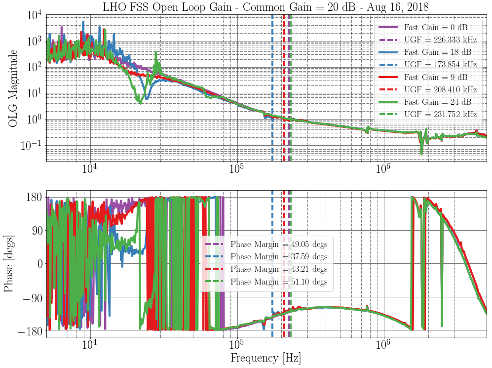
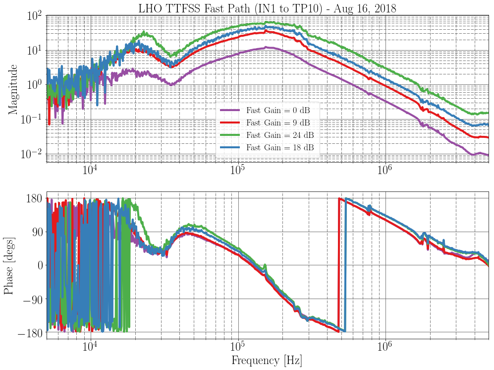
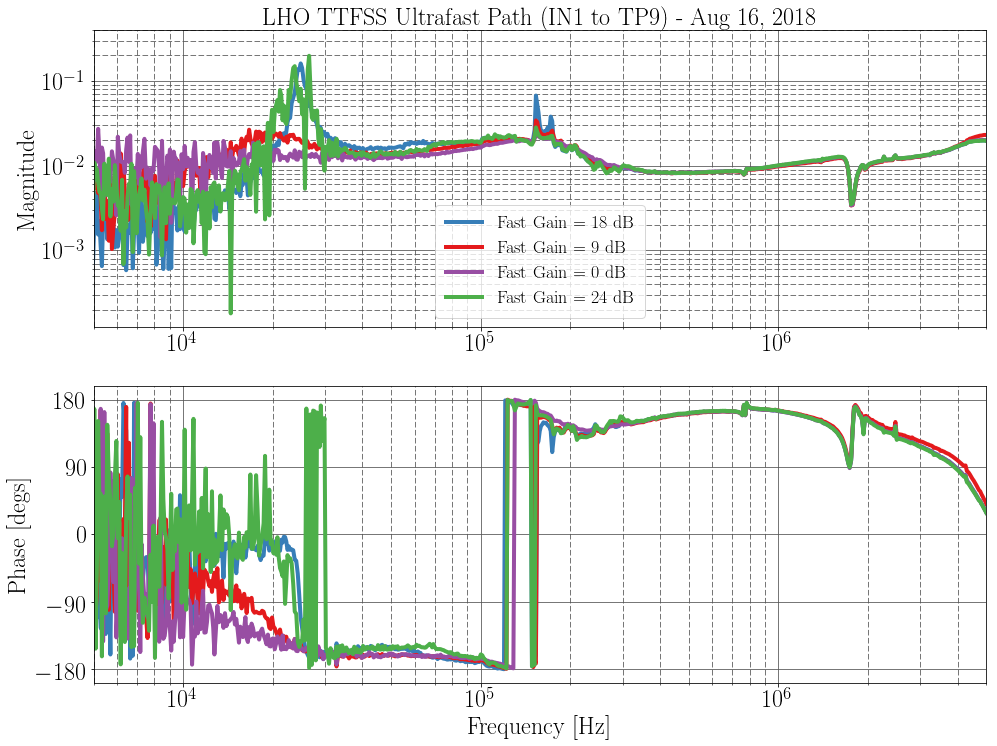
Peter K, Craig

We've been thinking about the stability of our CARM loop, since we recently had to lower the gain of our IMC from 100 kHz to ~30 kHz to avoid IMC locklosses.  The CARM frequency noise suppression at this level should still be fine, but we should be able to push the CARM UGF to at least 20 kHz as we acquire and the IMC should not limit us.  However, cursory investigation of the IMC yielded no immediate solutions, so a deeper look into the CARM loop is required.

Peter K took some TFs through the FSS while changing the fast gain.  Attached is the FSS OLG, TTFSS Fast (PZT) and Ultrafast (EOM) paths.  The TTFSS schematic currently in use at the LHO PSL lives here.

The FSS in it's current state seems healthy and stable.  We probably could stand to increase the UGF slightly.

We are currently running the FSS loop with common gain of 20 dB and fast gain of 9 dB.  With those settings, we have an FSS UGF of ~200 kHz (Plot 1), which is slightly lower than before.  Changing the fast gain does not affect the UGF.
There is a gain dip at 20 kHz that develops when the fast gain is turned too high, probably as a result of the PZT fighting the EOM.

In plot 2, for gains above 9 dB, the fast gain appears to not be able to further amplify the fast signal.  In plot 3 we see the 20 kHz hump develop in the ultrafast EOM path as we increase the PZT gain.
Images attached to this report
Comments related to this report
Actually the test point transfer functions were in through TEST 2 and out through either TP9 or TP10.
The stability of the FSS tends to be an issue of actuator range more than transfer function. In particular, the phase correcting Pockels cell has a very limited range. Once the Pockels cell saturates, the fast path isn't stable on its own. There was some work done in the TTFSS v4 to minimize the signal going to the Pockels cell at frequencies around and below the crossover.
In the past, we typically run both FSS and CM below the maximum bandwidth, until we were locked stably in high power and low noise. This was necessary because of excess frequency noise coupling at the very high end of the spectrum.