There have been some doubts about the stability of the REFL WFS DC centering loops, so I continued the work described in 43451 and optimized the loops even further. In summary
- Measured the plant transfer function for DC1/2 pitch/yaw and fit a model
- Designed a control filter that gives us a UGF of about 10 Hz, 60 degrees of phase margin, unconditionally stable loop for low gain, about a factor 3 of gain margin in the increase gain direction
- Measured the open loop transfer function and confirmed that the loops behave as modeled
Details
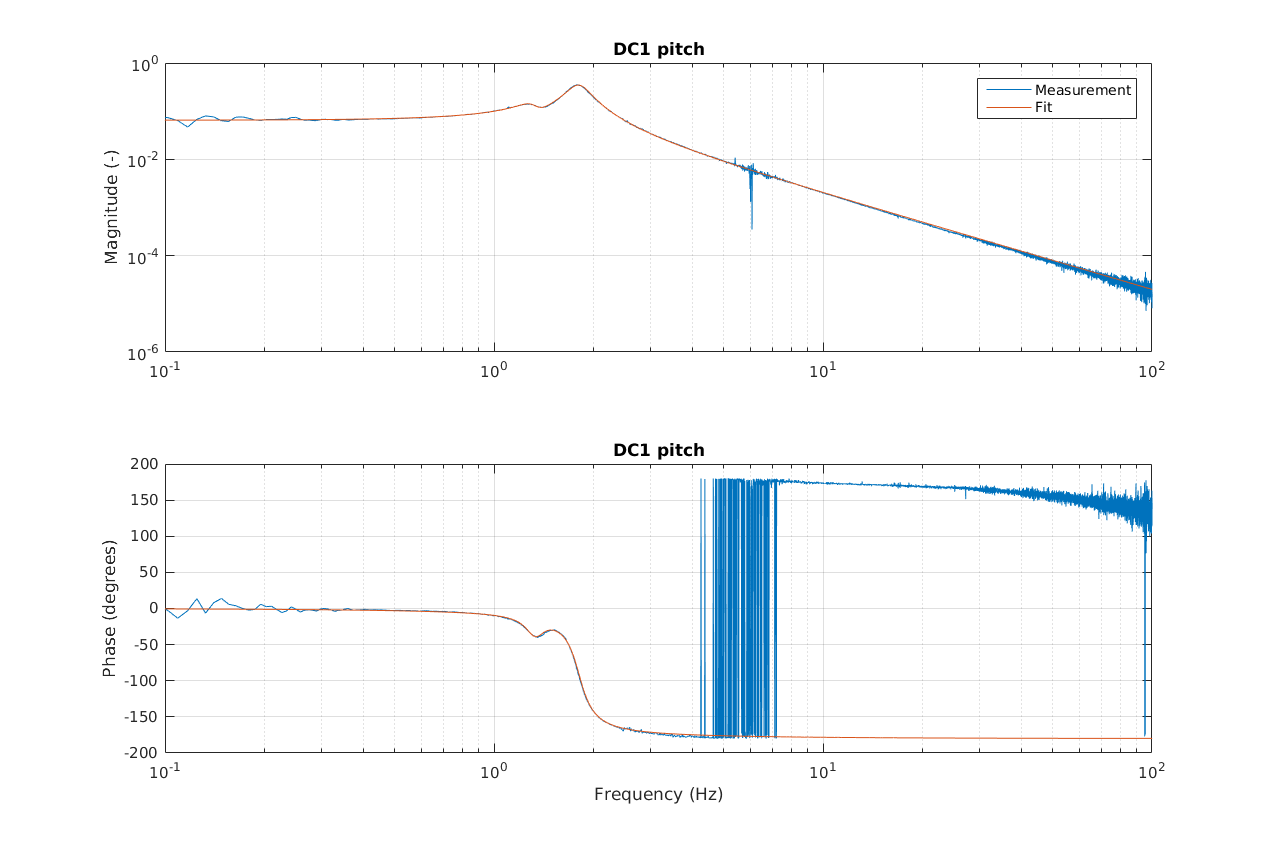
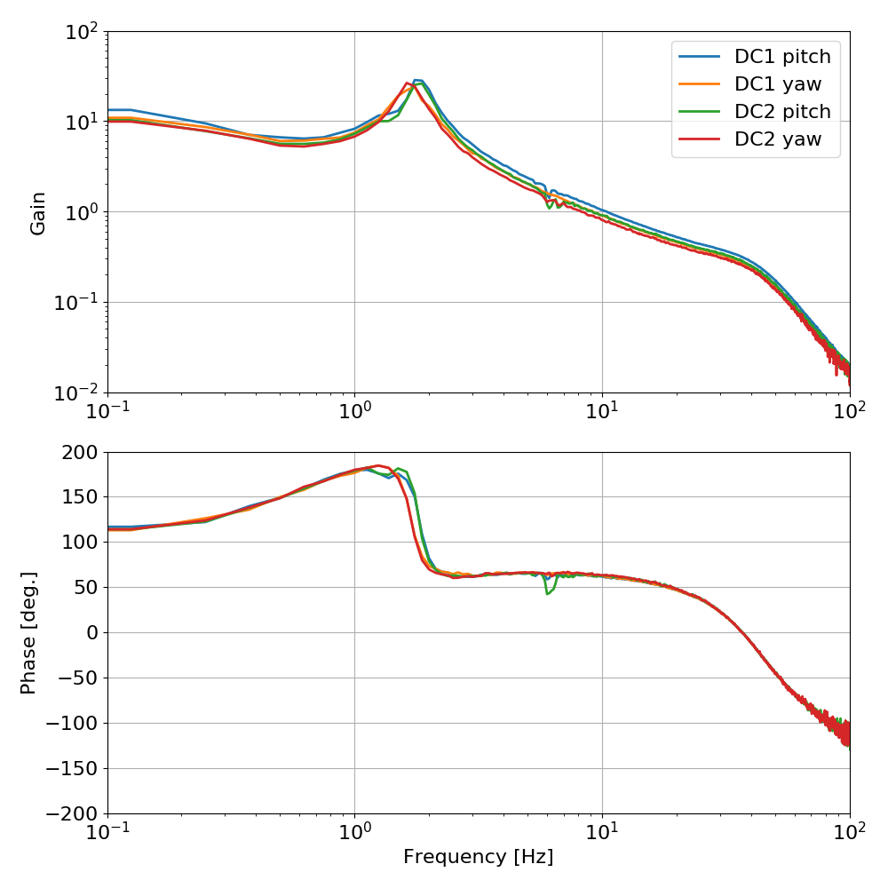
Plant measurements and fits
First of all, I measured the four plants. To do this I misaligned the ITMs and aligned the PRM, to have a single bounce beam. The beam was roughly centered on both REFL WFS. I then switched off all DC1 and DC2 loops, set their gains to 1, switched off all filter banks, including the integrator in the RM1 and RM2 suspensions. In this configuration I could inject an excitation in the DC1/2 pitch/yaw control filter banks and actually measure the plant with IN2/IN1.
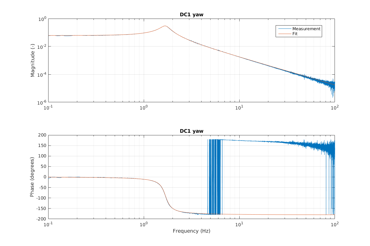
I loaded the measurements in MATLAB and used vectfit to fit them. The yaw transfer functions were very well fitted with a single complex pole, while the pitch transfer functions showed two complex poles and a complex zero. Measurements and fits are shown below.
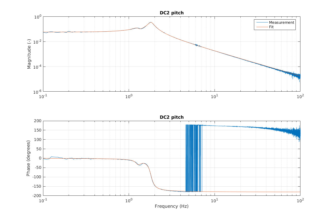
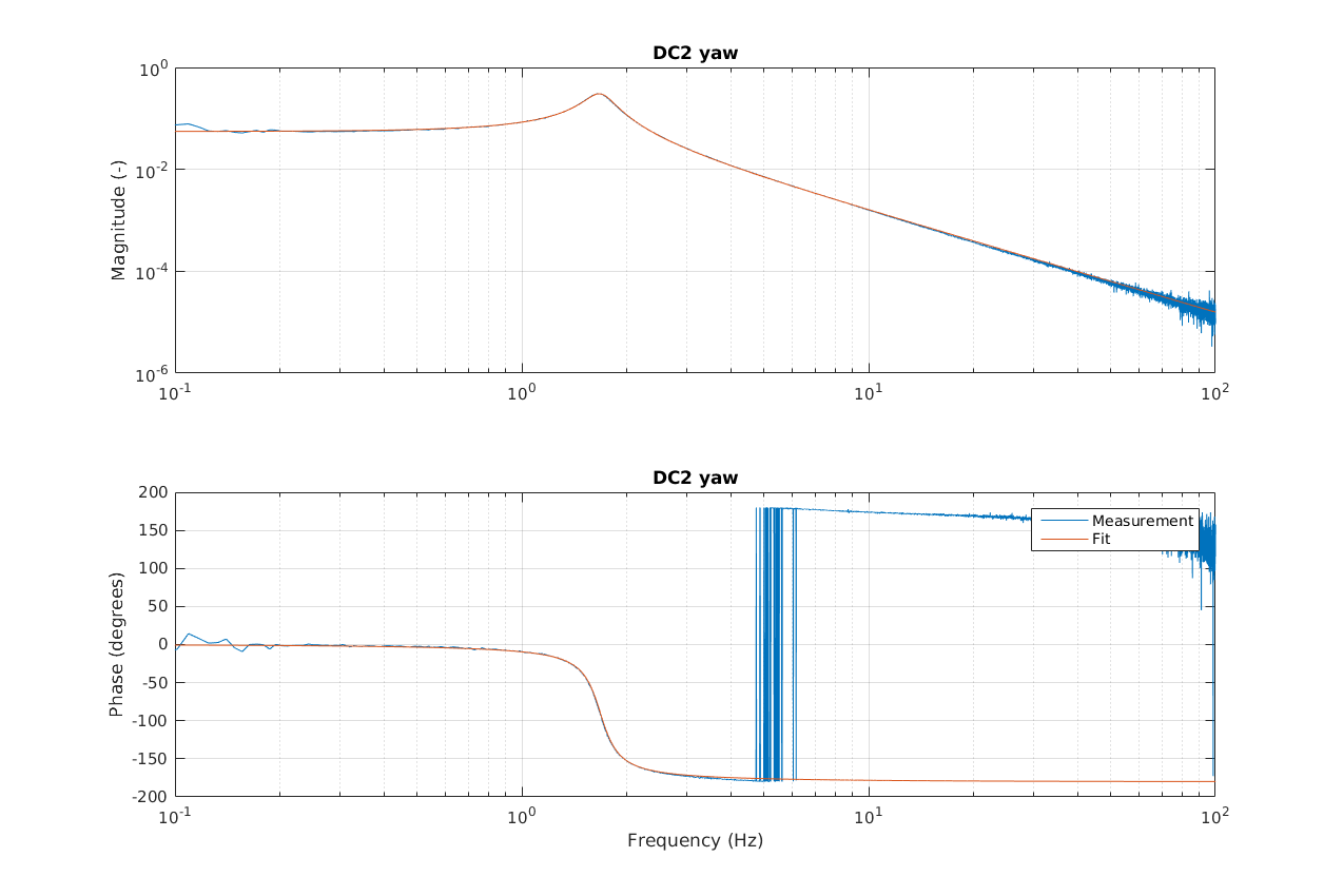
The table below gives the fit parameters
| Zeros [Hz] | Poles [Hz] | Gain at DC | |
|---|---|---|---|
| DC1 pitch |
-0.1042 + 1.3570i |
-0.1050 + 1.3117i -0.1050 - 1.3117i -0.1464 + 1.8066i -0.1464 - 1.8066i |
0.0649 |
| DC2 pitch |
-0.1118 + 1.3062i |
-0.1056 + 1.2627i |
0.0568 |
| DC1 yaw |
-0.1745 + 1.6794i |
0.0613 | |
| DC2 yaw |
-0.1540 + 1.6779i |
0.0554 |
Loop design
Using the fit models, I used MATLAB's sisotool to design simple single-input single-output control filters. The same control filter can be used for pitch and yaw, and it simply consists of two real zeros ay 0.83 Hz, one integrator, and a complex pole at 43 Hz with a Q of 1.4. The design is shown in the figures below, for both pitch and yaw. The figures from MATLAB's sisotool show the modeled open loop transfer function (upper adn lower right), the root locus (upper left), and the Nichols' plot (lower left).
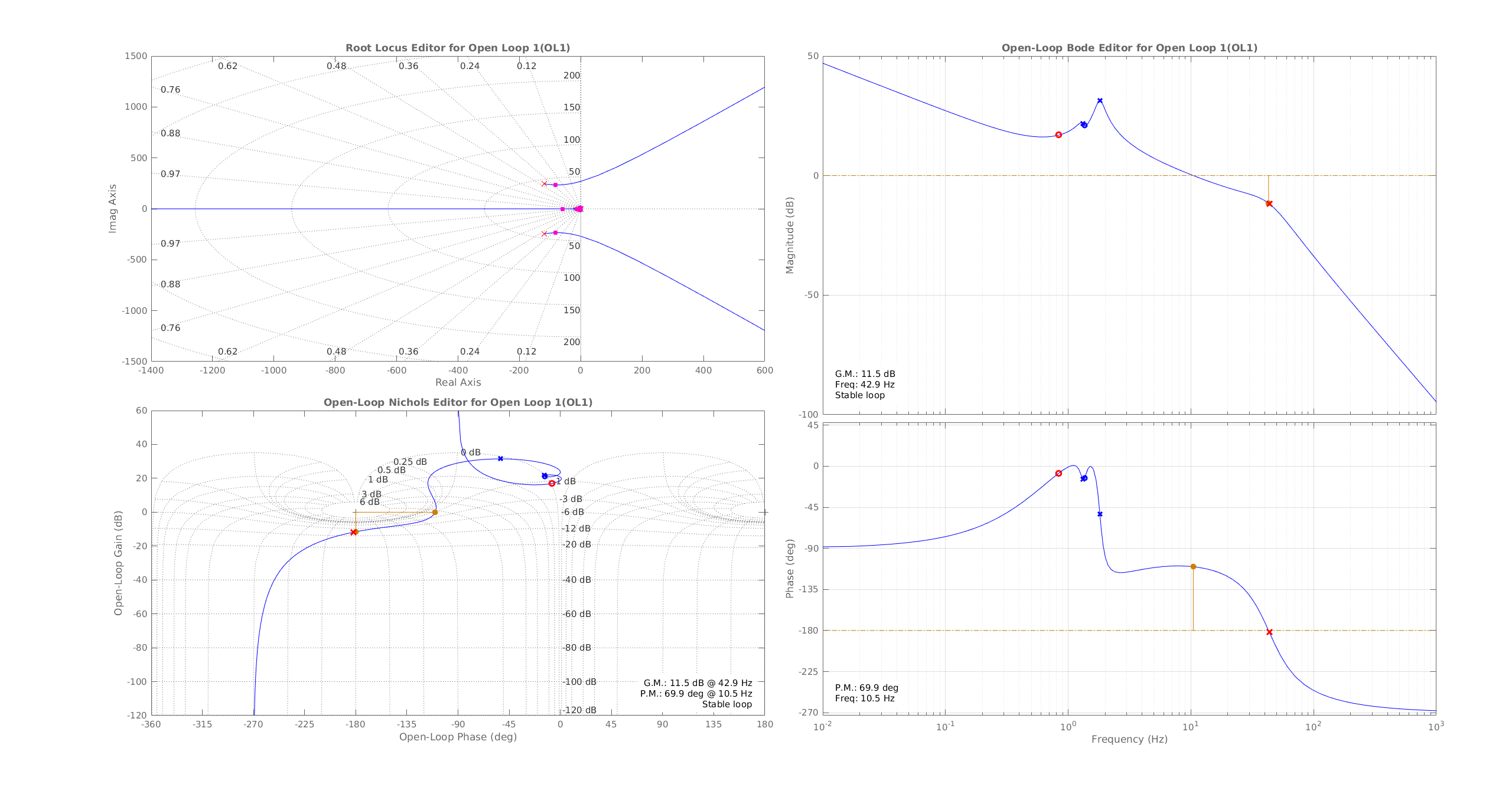
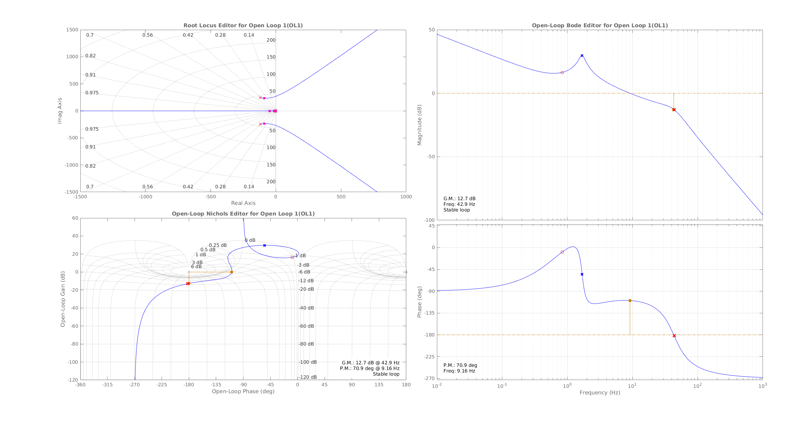
The model predicts a UGF of about 10 Hz, with a nominal gain of -1 in all the DC1/2 pitch/yaw filter banks. The loop is stable for all small gains, and the gain can be increased by about a factor 3 above the nominal value. The phase margin is more than 60 degrees for all values of the gain smaller than 1. There is plenty of margin for boosts or high frequency roll-offs.
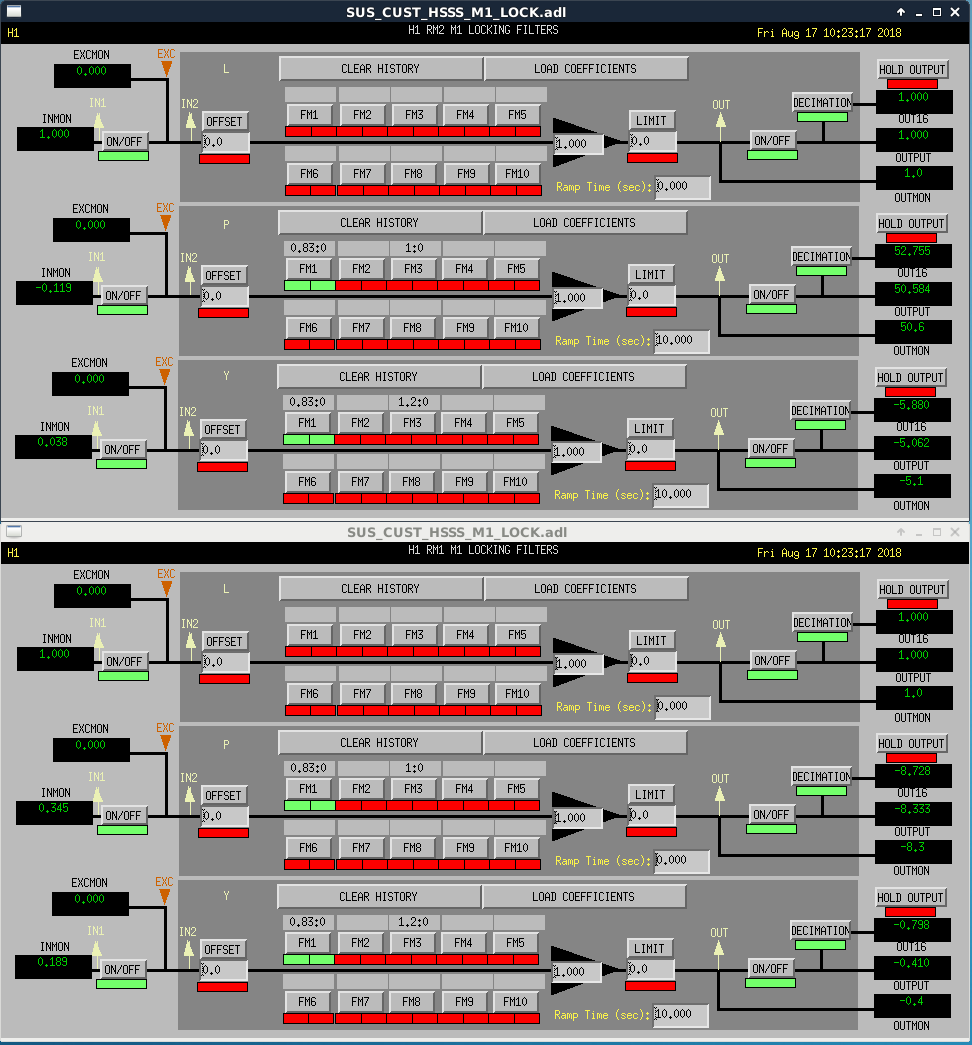
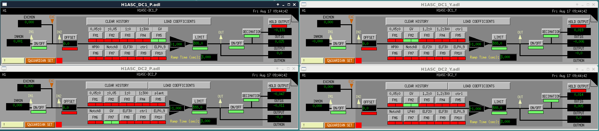
Filter implementation
The integrator and one of the two zeros at 0.83 are implemented in the RM1 and RM2 suspension filter banks (FM1 of H1:SUS-RM1_M1_LOCK_P and H1:SUS-RM1_M1_LOCK_Y).
The rest of the filter is implemented in the DC1/2 pitch/yaw filter banks (wherever I could find a free FM, or a FM which did not look like it was used or useful).
The configuration is shown below
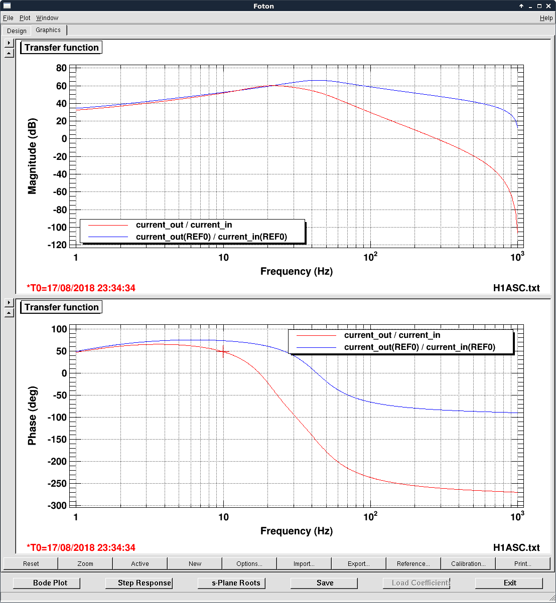
Loop performance measurement
I could engage the four loops with the nominal -1 gain without any problem. Then I measured the open loop transfer function by injecting white noise (band-passed between 0.1 and 100 Hz, boosted at low frequency with a 1/10 Hz second order filter). The measurements confirm the model prediction, as shown below
[Hang, Gabriele]
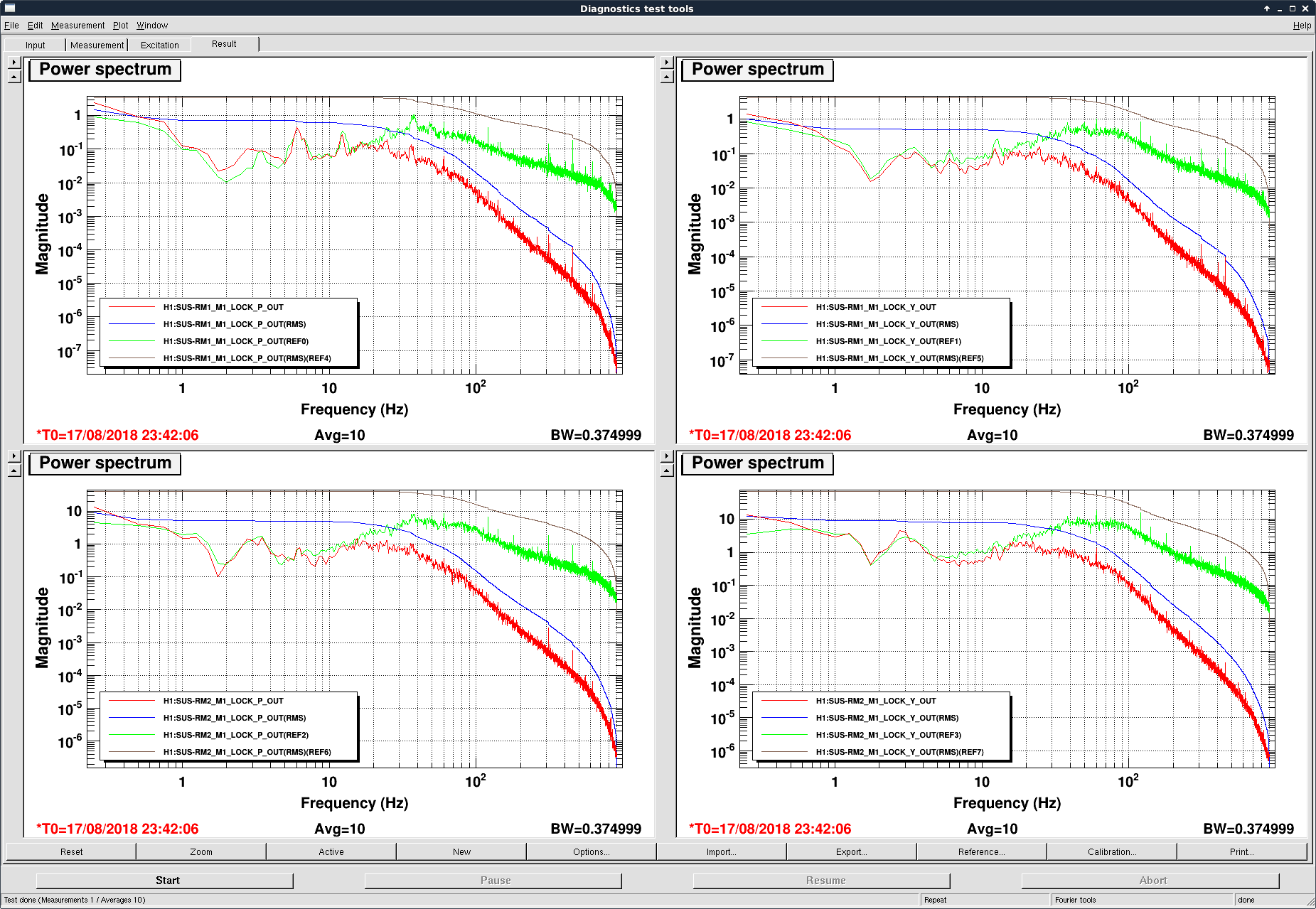
The audio alarms were often complaining about saturation of the HSTT, which we suspected to be due to the high frequency content of the new DC1 and DC2 centering loops. Following Hang's suggestion, we added a low pass filter (Chebychev Type 1, 25 Hz, 2nd order, 3dB band pass ripple).
This reduces the phase at 10 Hz by 25 degrees.
We also reduced the overall gain by a factor of two. In this configuration the UGF is 5 Hz (at 10 Hz we could see a bit of gain peaking just below 10 Hz).
The high frequency control signal to the RM1/2 is much lower, although the total RMS is reduced by a factor 2-3 only.