In summary, following the same method used for the REFL DC centering loops, I measured and optimized the AS_A and AS_B centering loops (DC3 and DC4). The loop design is the same used for the REFL WFS, with a bandwidth of about 5 Hz and it includes the additional low pass filter at 25 Hz.
Details
Output matrix diagonalization
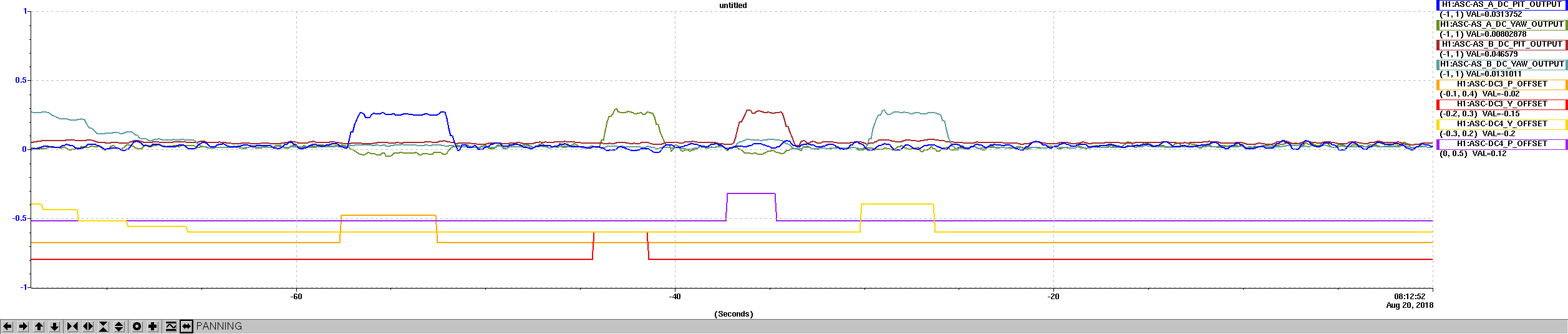
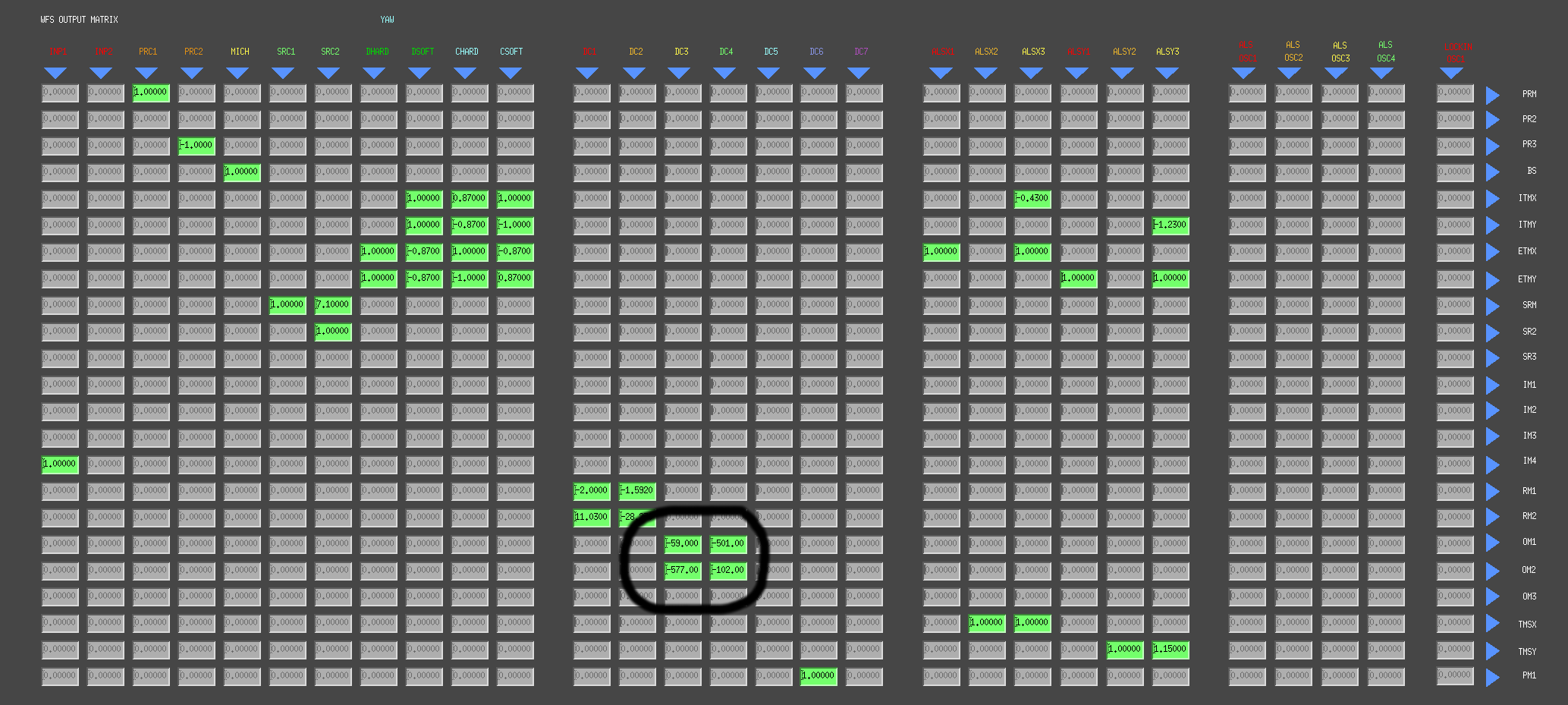
Following the same procedure described in 43451, I measured the DC response of the DC3 and DC4 loops, by adding offsets to OM1 and OM2. The figure below shows the resulting diagonalized output matrix. The original matrix was close enough.

Plant transfer function measurements
Although there was no reason to expect the OM's to behave differently from the RM's, I measured again the plant transfer function, using the same procedure described in 43488. It turns out that the frequency dependence is quite similar to the RM's, but there is a large difference in the overall gain: the OM responses is about 50-100 times larger than the RM responses, in terms of QPD normalized signals over OM motion. Not surprising, since the optical path from the OM's to the AS WFS is different from the optical part from the RM's to the REFL WFS. The plot below shows all four OM responses.
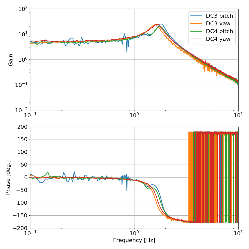
Below the fit parameters
| Zeros [Hz] | Poles [Hz] | Gain at DC | |
|---|---|---|---|
| DC3 pitch |
-0.1001 + 1.4090i |
-0.1224 + 1.3754i |
4.1480 |
| DC3 yaw |
-0.1630 + 1.6067i |
4.6743 | |
| DC4 pitch |
-0.0881 + 1.3958i |
-0.0952 + 1.3583i |
4.8371 |
| DC4 yaw |
|
-0.1766 + 1.6754i -0.1766 - 1.6754i |
4.8371 |
Loop design
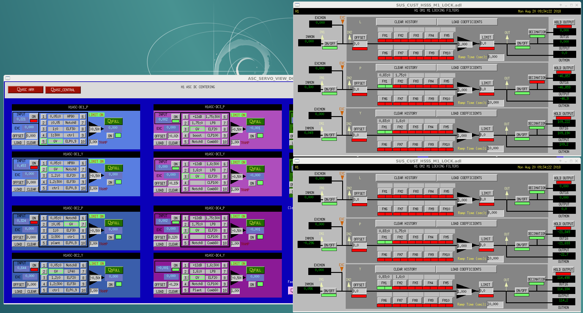
I used exactly the same control filters that were described for DC1 and DC2 in 43488, the only difference being in the overall gain. Those filters also include the low pass at 25 Hz, described in 43501.
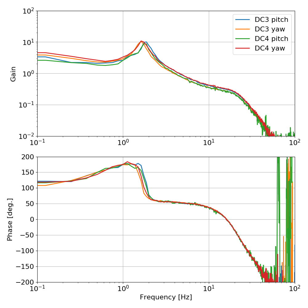
I measured the open loop transfer function of all four loops and found no surprises: the loop are stable for all low values of the gain. With a gain setting of -0.5 in the DC3 and DC4 filter banks, the UGF is about 5 Hz for all loops. I did not fine tune the gains to have exactly the same bandwidth. The differences are small.
The configuration of all filter banks and switches is shown in the file attached.
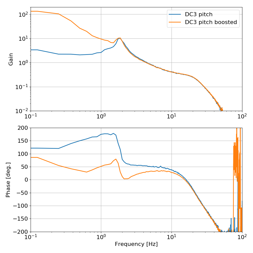
Boost
Just in case we need more low frequency gain in the centering (not sure why...), I experimented on a boost (complex pole at 0.3 Hz, complex zero at 1.8 Hz). With this boost on the loop is clearly no more stable for all values of low gains, but margins are still reasonable.