J. Oberling, C. Vorvick, P. King
Quick Summary
The DBB is still not fully operational. We have an alignment we think is OK, but are still unable to lock the DBB PMC. There are a couple reasons for this (detailed below), which will be looked into the next time the DBB is worked on.
Details
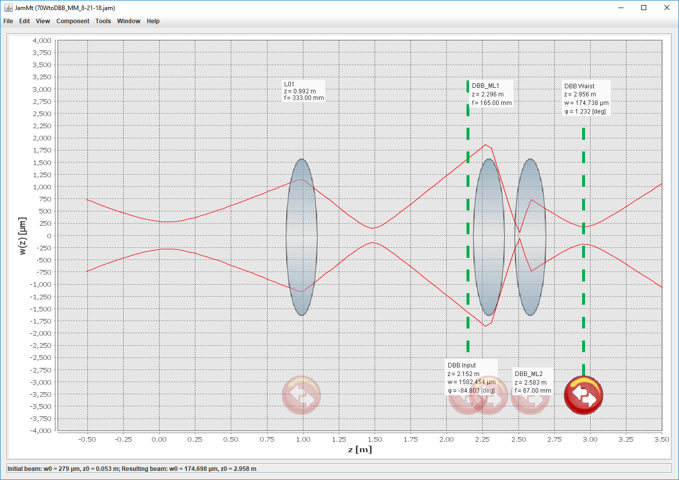
Today we concentrated on resurrecting the 70W path of the DBB (the old beam path for the HPO) so we can take measurements of the 70W amplifier. Peter took a beam propagation measurement for the 70W amplifier and performed a fit. I then took his results and used JaMMT to find a mode matching solution (see 1st attachment; 0 is the front face of the 70W amplifier). I then removed the existing DBB mode matching lenses and aligned the 70W beam into the DBB using the 2 irises along the input rail. The mode matching lens holders were moved to their respective spots from the solution and the lenses installed. Cheryl and I then worked on the beam alignment into the DBB PMC after lunch. This took much back and forth and most of the afternoon, but we finally got an alignment that we think is OK. Unfortunately the DBB PMC would not lock. I think there are 2 reasons for this:
- 1) Higher-order mode content of the 70W beam is too high and/or the mode matching still needs some tweaking. I think both contribute.
- 2) Not enough power available to the DBB
1) The DBB PMC has a CCD camera on one of its output ports that is used to watch the modes output while the cavity scans (aids in alignment). We hooked a monitor up to this CCD camera and swept the cavity at 1Hz. Watching the modes go by there were many different radial-looking modes that I don't remember being there last time I did this for the HPO in 2016. Looking at an FSR scan on an oscilloscope, there were several peaks that I don't recognize either. The usual 01 and 10 alignment peaks were there (which we worked to minimize), as well as the peaks that denote mode matching (which were large, which is why I think the lens positions need to be tweaked), but there were also a number of large peaks that I don't remember being there with the HPO. Therefore the positions for the DBB mode matching lenses definitely need to be tweaked, but I also think (based on these other peaks I don't recognize) we need to work on improving the mode matching into the 70W amp.
2) Regardless of 1 above, we do not have enough power available to the DBB. The maximum available right now is 63 mW (measured with a 3W power meter); the DBB needs at least 120 mW. This is because of the change from the HPO to the 70W amplifier (while it needs to be updated to reflect the 70W amp installation, T0900610 can be used to see the locations of the mirrors I'm about to discuss). The DBB uses a leakage beam from mirror M03, which has a transmission of 0.2%. This leakage beam is then routed to the DBB via mirrors M12, M14, and M11 (in that order). M12 and M14 both have small leakages (1% and 0.2% respectively), but M11 is a 50/50 beam splitter. This is needed as the 35W FE beam also needs to make it into the DBB (it transmits through M11, while the 70W amp beam reflects off of M11). So with 70W output from the amplifier, the leakage through mirror M03 is only 140mW. The beam then loses 50% at M11, which does not leave enough light for the DBB. In the short term, just so we can make measurements on the 70W amplifier, we can replace M11 with an HR mirror. In the long run, however, we will have to replace mirror M03 to allow more light into the DBB.
Note: The DBB is experiencing the same problem we had in the lead up to O2; as soon as the button to open the DBB internal shutter is clicked, the DBB goes into INTERLOCK and will not function until reset (going to STANDBY clears the interlock). We got around this today by moving the internal shutter, but this does need to be looked into. Looking at past alogs after leaving the enclosure, it seems this was cured by unplugging the offending shutter and plugging it back in. Next time the DBB gets worked on, this will be tried to see if it fixes the problem.
Steps to be taken next time the DBB is worked on:
- Unplug/plug in the DBB internal shutter
- Replace mirror M11 with a HR mirror
- Tweak DBB mode matching lens positions
- Tweak alignment again
- Attempt various DBB measurements
- At a minimum we want to be able to take Mode Scan measurements so we can see the higher-order mode percentage of the 70W amplifier output