craig.cahillane@LIGO.ORG - posted 03:13, Thursday 23 August 2018 (43613)
Locking tonight
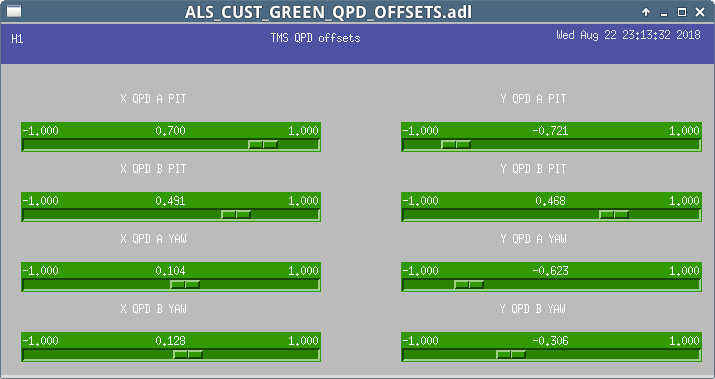
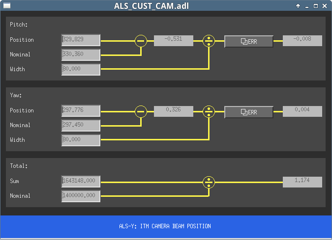
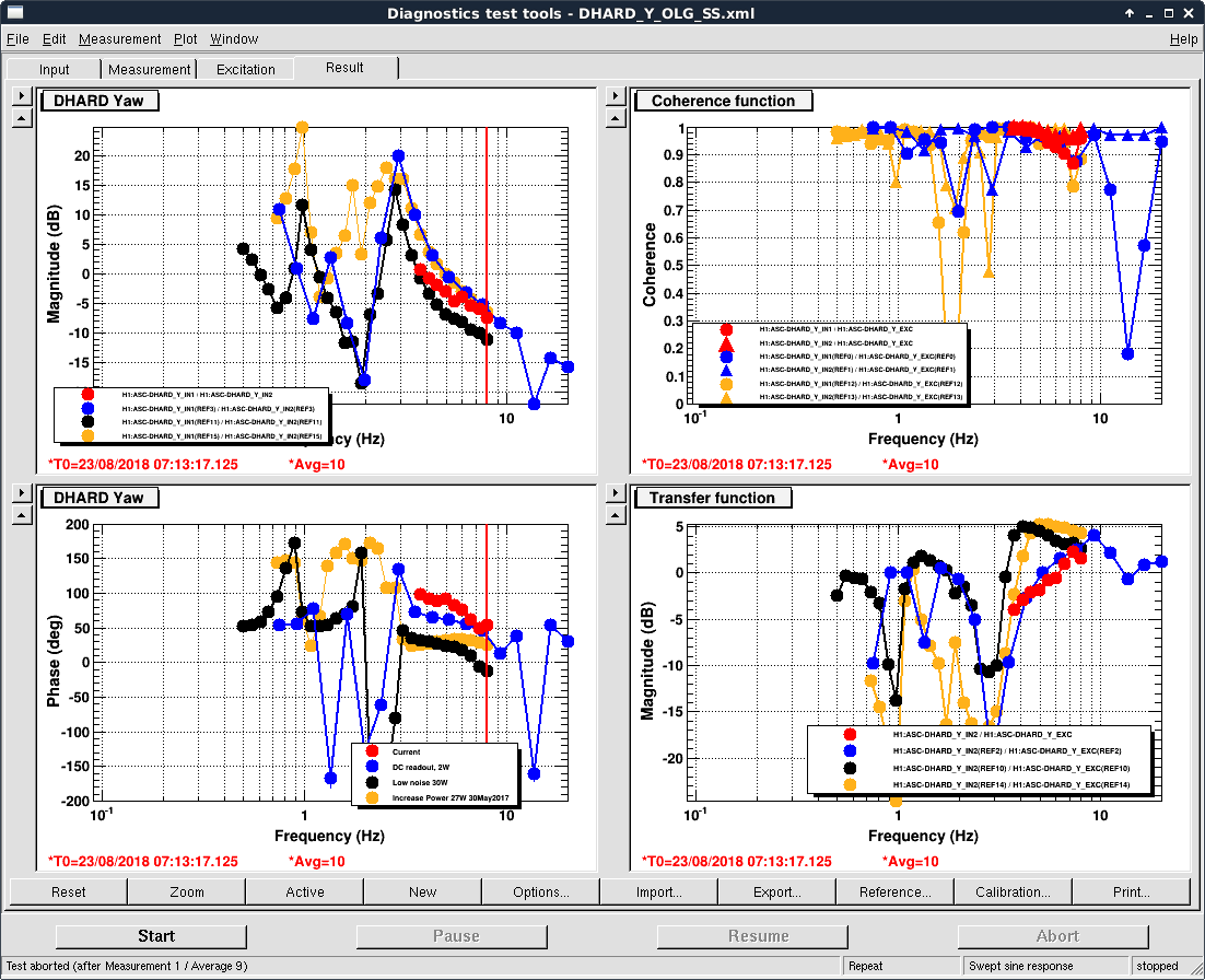
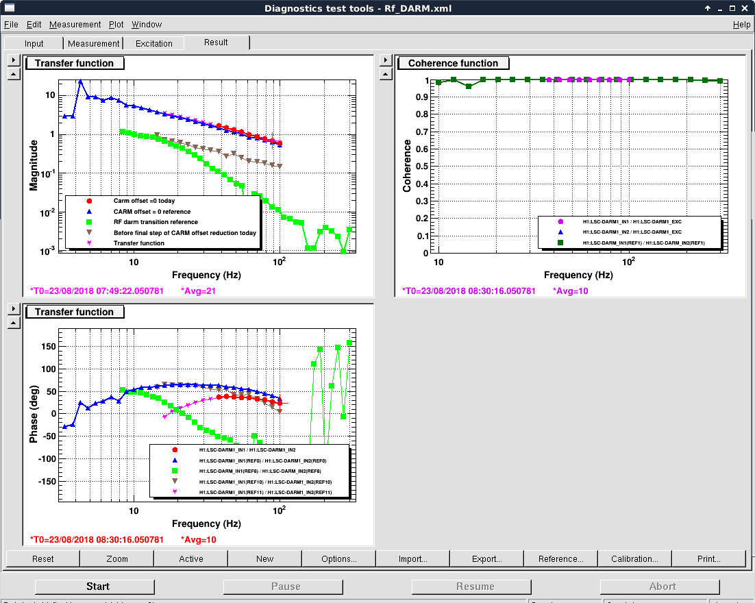
Sheila, Craig

- We reset the green QPD offsets and green ITM camera positions while sitting on Full IFO with five ASC loops closed (CHARD, DHARD, MICH, PRCL2, INP1).  Pics 1 through 3 show those new settings.  We accepted them to SDF.

- DHARD_Y was oscillating at about 0.1 Hz, so we took a DHARD_Y TF and found the gain was about a factor of 2 low, with UGF ~ 3 Hz.  DHARD_Y gain was increased from -40 to -80, and we retook the measurement, giving a UGF ~ 4 Hz (Pic 4).  This worked really well for stabilizing the buildups (Pic 5), so we added it to guardian.

We are having trouble with the DC_READOUT transition
- Our RF DARM sensor is ASC-AS_A_RF45_Q_SUM_NORM (hereby called ASQ).  We are trying to transition to LSC-OMC_DC_OUT (now called OMC).  If we use DARM noise to take the TF between the two sensors, we get something that looks like Pic 6, with a 1/f dependence for ASQ/OMC at high frequencies.  We see ASQ WFS sensor noise impressed upon OMC.
- So we have to take a driven DARM TF measurement to get the true TF between ASQ and OMC.  We got a gain of about 58 with no sign flip.
- Since the ASQ sensing matrix element is -1e-6, we expect the OMC matrix element to be -5.8e-5
- We then tried a 1/2th transition, which is where you blend your error signals using 1/2th of the sensing matrix element you'd expect for the new sensor and 1/2ths of the old sensor's matrix element.  So we put in -0.5e-6 for ASQ, and -2.9e-5 for OMC.
- When we did this, the OMC transmission increased, indicating to us that our DARM offset had increased.  Our DARM offset in LSC-DARM1 is 9e-5.
- We measured our DARM TF and found the gain was increased by 1.47.
- To maintain the same DARM gain, we calculate our OMC matrix element should be -2e-5 when completely controlled using OMC DCPDs.
- So we redid the half transition, yielding Pic 7, which matched our RF DARM OLG very well, but the power on the DCPDs increased to about 30mA from about 11mA before we started to transition.
- However, we are still not sure why our DARM offset should become larger when the DARM OLG remains the same.  We have ensured that RF DARM cts = DC DARM cts.  Sheila suspected the dark offsets of ASQ, but after a bunch of OMC scans at different DARM offsets it seems like DARM1 offset of zero really is zero.
- In our last DC READOUT transition attempt, it seemed like we didn't have any real feedback from the OMC DCPDs to DARM.  We changed the OMC matrix element, but saw no change in the DARM OLG.  This could explain this DARM offset business, but before we were able to maintain the gain, so unclear what's happening.
Images attached to this report