The Birmingham low-frequency workshop participants
Motivation:
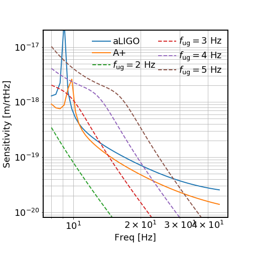
The ASC noise dominates DARM below 30 Hz. To reduce this noise, we need to reduce the control bandwidth as much as possible (at least in the final low-noise state). In the first attached figure we show the aLIGO/A+ design sensitivity and ASC noise projections for different UGFs. Here we only consider a single DOF, assuming that the sensing noise is 5e-15 rad/rtHz and the a2l coupling is 1mm/rad. For each loop we low-pass it as aggressively as possible so that the phase margin is 30 deg. The point is that if we want to reach the design sensitivity, we can at most have an ASC UGF of 3 Hz.
On the other hand, we need to have sufficient gain to suppress the residual mirror motion to maintain the IFO at its working point. Yet what defines 'sufficient gain', and how much RMS motion of each dof can be tolerated? Here we explore what kind of requirements should be set on the RMS angular motion, which can then be converted as requirements on the minimum ASC loop bandwidth given a seismic configuration.
=======================================================
ARMS:
1). DARM sensitivity requirement -- ARM buildup
Note that while the shot-noise-limited DARM sensitivity scales with input power as sqrt(P_in), it scales LINEARLY with ARM buidup (see, e.g., https://arxiv.org/abs/1702.03329, eqs. 1 and 7). This means that if we lose x% buildup, we will lose x% DARM sensitivity.
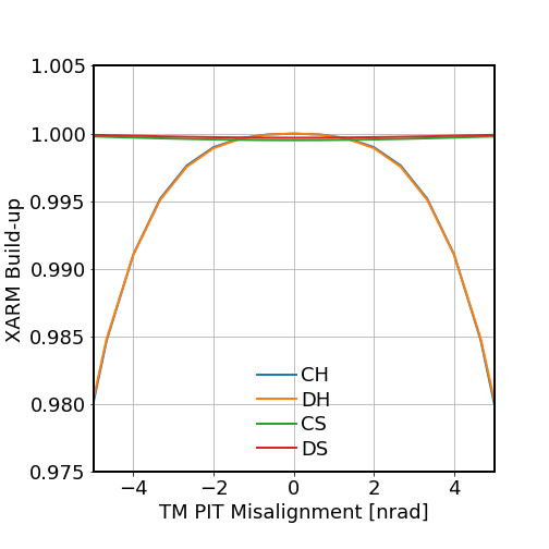
In the second plot we show how the ARM buildup varies with respect to misalignment rms for different dofs. Here we define 1 HARD = 1 * ETM + 0.87 * ITM, and 1 SOFT = 1 * ETM + 1.15 * ITM. We see that the buildup is mostly sensitive to the hard mode misalignments and for CH/DH, 3 nrad rms for each dof seems to be good enough as we would only lose 0.5% DARM sensitivity.
2). DARM sensitivity requirement -- A2L coupling
The RMS angular motion leads to a RMS spot position on the TM, which can then couple with the AC angular motion to become a length noise (i.e. a2l). The gain is dy/d heta = -4.5e4 m/rad for the hard mode, and 2.1e3 m/rad for the soft mode. This means that for a 3 nrad of CH/DH, it creates a spot motion on the TMs of 0.14 mm. This is smaller than the DC miscentering from the pointing dof ~ 1 mm, and thus is not a major limitation. Nonetheless, it sets a limits on how well we can reduce angular noise based on a2l feedforward.
3). PR-CARM linear range
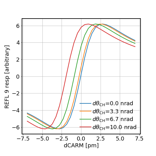
One concern people have in the workshop is that if the misalignment would reduce the linear range of high-finesse cavity PR-CARM. We thus perform a finesse simulation to see the CARM error signal with different CHARD misalignment. See the third plot.
From it we conclude that the linear range is not affected. The decrease in the optical (PDH) gain is also mild <1%. A small offset appears in CARM yet this is not an issue as the longitudinal loop will correct for it. Consequently, 3) is trivially satisfied once 1) is satisfied.
=======================================================
PRC:
4). PRC buildup
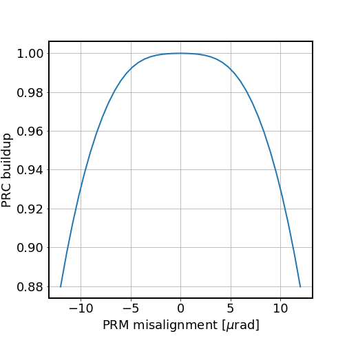
Here for simplicity we only consider misaligning PRM. The PR2/PR3 effects can be converted to PRM one accordingly (roughly speaking the conversion factor is the ratio of spot sizes on the PR mirror). In the forth figure we show the PRC buildup as a function of PRM misalignment. The shot-noise-limited DARM sensitivity scales as PRC build up as sqrt(G_prc). Thus it seems we can tolerate 7 urad of PRM misalignment, which corresponds to 2% decrease in PRG and 1% drop in DARM.
=======================================================
SRC:
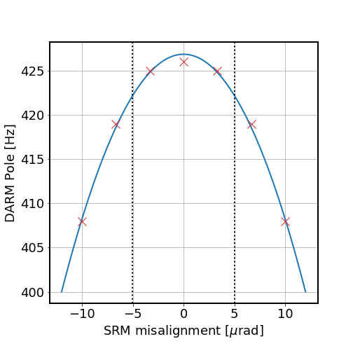
5). SR-DARM pole frequency.
The SR-DARM pole is affected by the SRC build-up. In the fifth plot we show how the DARM pole (assuming Tsrm=0.325, leading to a nominal pole at 426 Hz) varies with respect to SRM misalignment. If we want the darm pole to fluctuate within 1 Hz (3 Hz) then we need to control the SRC misalignment (after propagating SR3/SR2 to SRM) to 3 urad (5 urad).
=======================================================
(Controlling the angular RMS to a certain level is just one aspect of the ASC bandwidth requirement. The other requirement coming from suppressing the Sidles-Sigg radiation torque. Specifically, the hard mode needs to be controlled around its resonance which can be as high as 3 Hz @ 125 W input. Using a regular 1/f-like controller would require a UGF of 5.5 Hz which clearly would not meet the noise requirement...)
=======================================================
All the analysis codes available at (requiring an installation fo finesse to run it):
https://ldas-jobs.ligo.caltech.edu/~hang.yu/ASC/general/work_min_asc/
The differential arm cavity misalignment rms also couples jitter into DARM, see T1700080 and references therein.