Summary (aka TLDR)
- All test masses standalone angular response all consistent.
- The soft/hard angular driving matrix seems ok
- The yaw transfer functions as measured in full lock have a phase lag between 1.5 and 2 Hz which causes our gain increase issues
- This phase lag is not reproducible simply from the single mirror measurements plus soft and hard cavity geometry
- But assuming a spurious coupling of pitch and yaw for at least one mirror, we can get something very close to the bad phase lag
- This could be due to bad centering or bad A2L that couples pitch and yaw through the longitudinal control
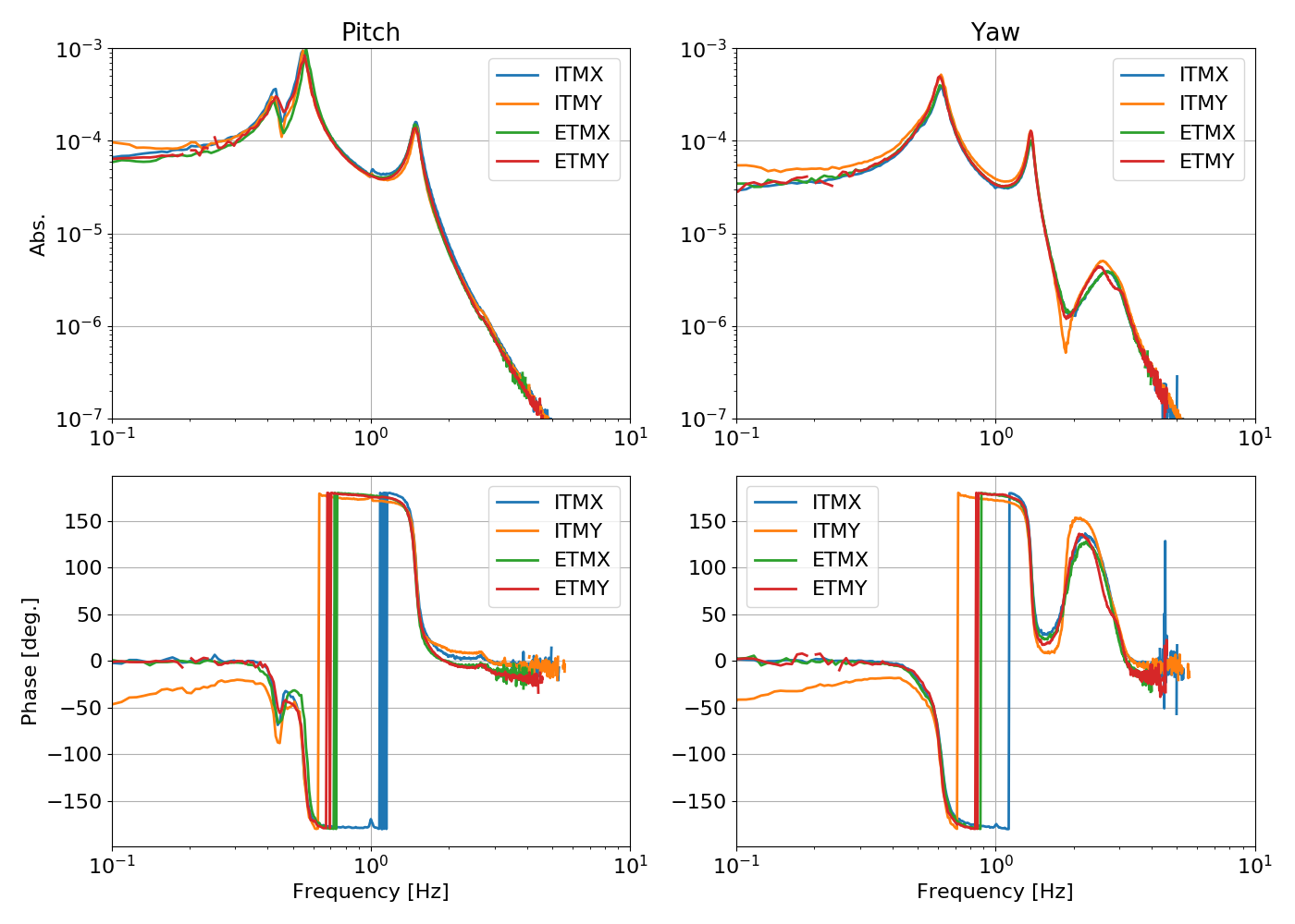
Updated single test mass responses
This afternoon I measured again the ETMY picth and yaw response, after the whitening was fixed. Now ETMY behave like all other test masses. Also, Sheila checked that the ITMY optical level calibration was wrong by a factor of roughly 2 (see 43816). Now the response in pitch and yaw of all four test masses is consistent. As a reminder, this response is measured by acting on each suspension individually, and injecting at the same point where the ASC control signal is entering the suspension model. Therefore the measurements below are good starting point to build the hard and soft degrees of freedom plants.
Reconstruction of hard and soft d.o.f.s
The reconstruction happens in three steps. First of all I copied the actuation matrixes from the ASC screen:
#           DHARD  DSOFT  CHARD CSOFT

Mat_PIT = [[-0.87,  1.00, -0.87,  1.00],   # ITMX

           [ 0.87, -1.00, -0.87,  1.00],   # ITMY

           [ 1.00,  0.87,  1.00,  0.87],   # ETMX

           [-1.00, -0.87,  1.00,  0.87]]   # ETMY
# DHARD DSOFT CHARD CSOFT
Mat_YAW = [[ 0.87, 1.00, 0.87, 1.00], # ITMX
[ 0.87, 1.00, -0.87, -1.00], # ITMY
[ 1.00, -0.87, 1.00, -0.87], # ETMX
[ 1.00, -0.87, -1.00, 0.87]] # ETMYThen I computed the geometrical combination of ITM and ETM motions that gives the soft and hard d.o.f.s. To do this, I computed the eigenvectors of the stiffness matrix of Sidles and Sigg. The angular conventions used in the paper are different from those used in the suspension. So for pitch the soft mode corresponds to a motion +ITM +ETM (meaning that both angles of the mirrors increases in value), while the hard mode corresponds to +ITM -ETM. In yaw the suspension convention for the angles is different, so we have that soft is +ITM -ETM and hard is +ITM +ETM.
PITCH =

[[-0.247  0.247  0.285 -0.285]

[ 0.285 -0.285  0.247 -0.247]

[-0.247 -0.247  0.285  0.285]

[ 0.285  0.285  0.247  0.247]]
YAW =
[[ 0.247 0.247 0.285 0.285]
[ 0.285 0.285 -0.247 -0.247]
[ 0.247 -0.247 0.285 -0.285]
[ 0.285 -0.285 -0.247 0.247]]I checked that by multiplying the driving matrix with my geometrical matrix I get a unity matrix. So our driving is consistent with the geometrical definition of soft/hard and common/differential, provided that all test masses have exactly the same response function.
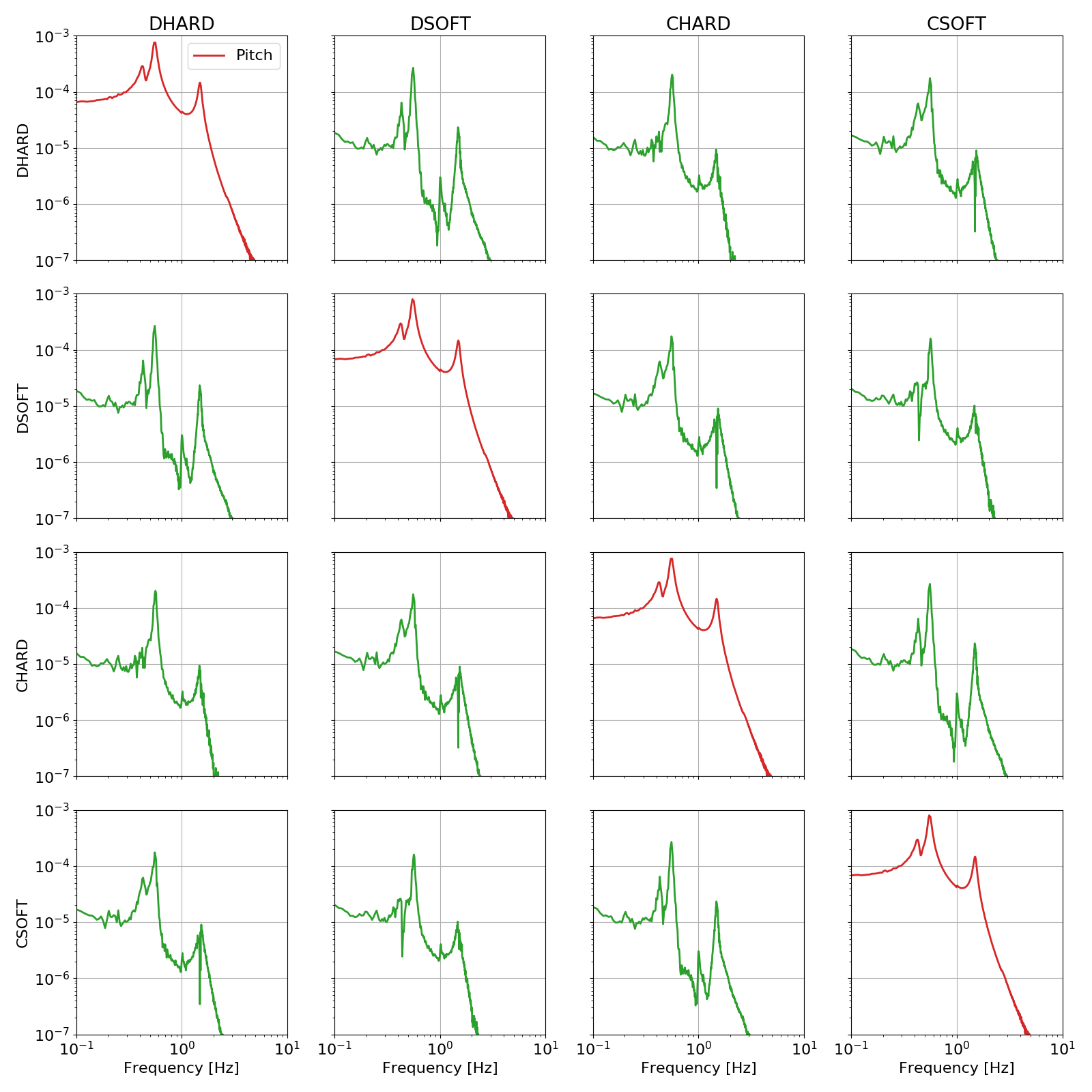
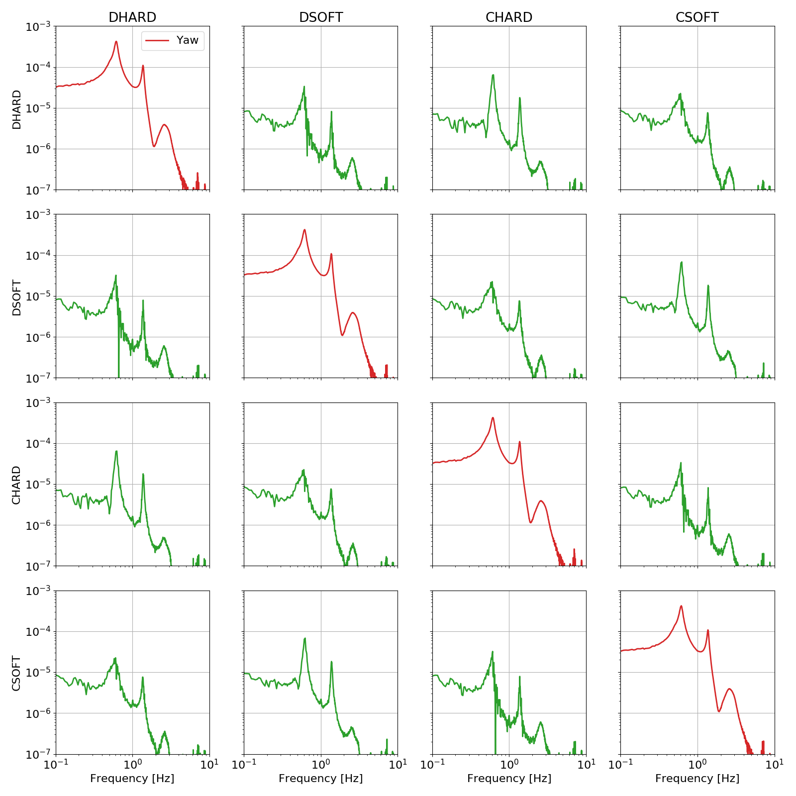
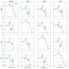
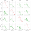
Using those results and the measurements, I can now compute the transfer function from driving of each d.o.f. to motion of each other d.o.f. The two plots below show that the actuation should be quite diagonal (left is pitch, right is yaw)
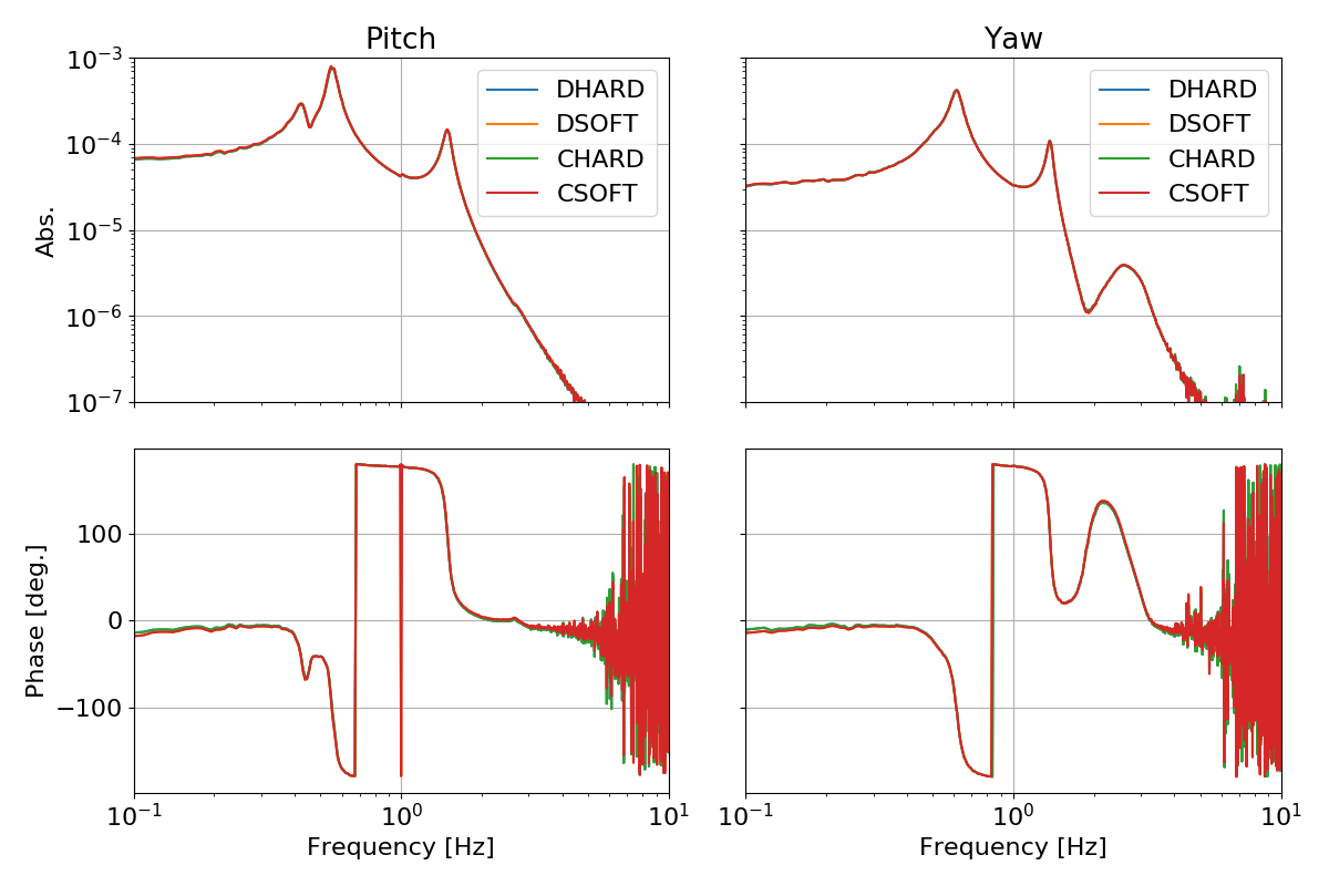
Neglecting the off diagonal terms, we can see that the measurements and the model give us the expected results that all d.o.f.s have the same pitch response and the same yaw response.
Comparison of single+model with full IFO measurements
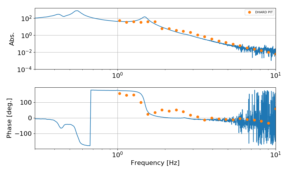
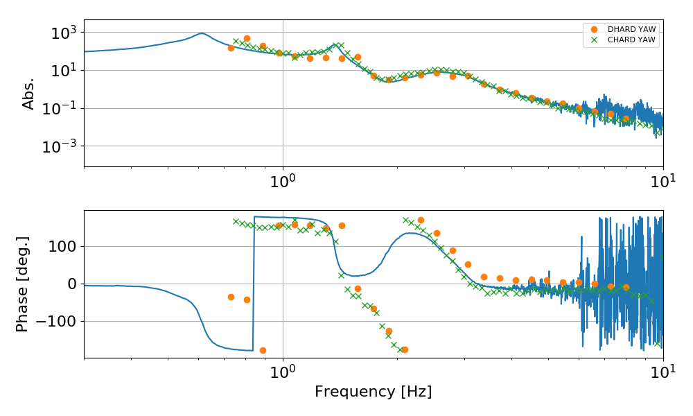
We have measured good quality transfer functions of DHARD pitch and yaw, and of CHARD yaw, with the ASC loops closed, in full lock, at 2 W input power. Apart from a global scaling and possibly a sign (I didn't track all gains), we have the comparison below for pitch and yaw (those plots show the plant transfer function, which are obtained from the measured OLTF in full lock by factoring out the control filter):
One could argue that the full IFO pitch transfer function is not very different from the one reconstructed from the single mirror measurements, apart from a phase bubble around a couple of Hz. However, for yaw:
- DHARD yaw and CHARD yaw give consistent measurements in full IFO
- They both show a significant deviation from the single mirror reconstruction, in the form of a large phase rotation between 1.5 and 2 Hz. As already pointed out earlier, this is the origin of our problems.
So we cannot reconstruct the yaw CHARD and DHARD responses from the single mirror responses: there is something missing here
One possible explanation: pitch-yaw cross coupling
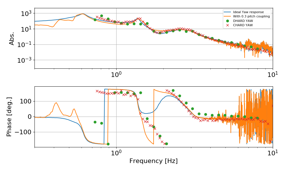
If we take one mirror, and mix a fraction (20-30%) of the pitch transfer function with the yaw transfer function (I know this sounds like a cooking recipe, but bear with me), then we can produce a phase lag very similar to what we measure:
To produce this I had to assume that the yaw response of ETMY is a mix of the yaw an pitch response. The amount is not very important, as it changes a but the shape. Here I also assumed a coupling described by a frequency independent constant, while it is more likely to have some frequency dependency.
A possible origin of this coupling could be due to bad A2L, which couples yaw and pitch to longitudinal. Maybe we don't even need to involve pitch, and a mixing of yaw and longitudinal degrees of freedom might be sufficient. I don't have a measurement of the longitudinal actuation, so I can't model this.
