Prompted by a discussion with Gabriele, I took some measurements of the first loop power stabilisation.
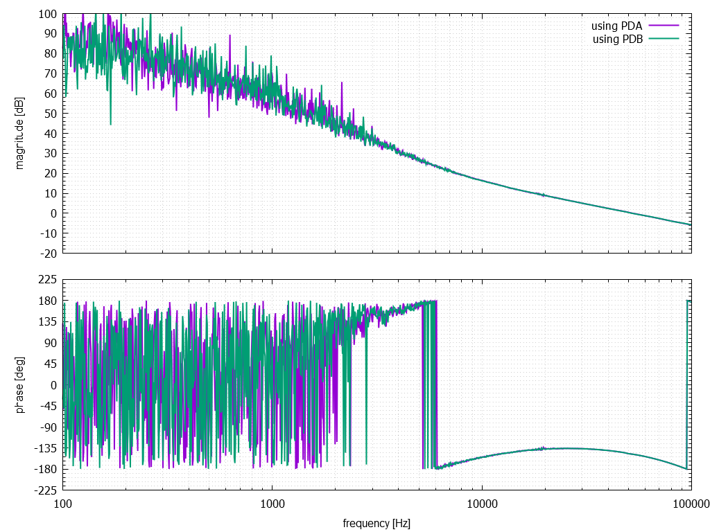
isstf.png shows the transfer function using either PDA or PDB (ie, either of the two first loop
photodiodes). No difference in the transfer function was observed. The UGF was around 50 kHz.
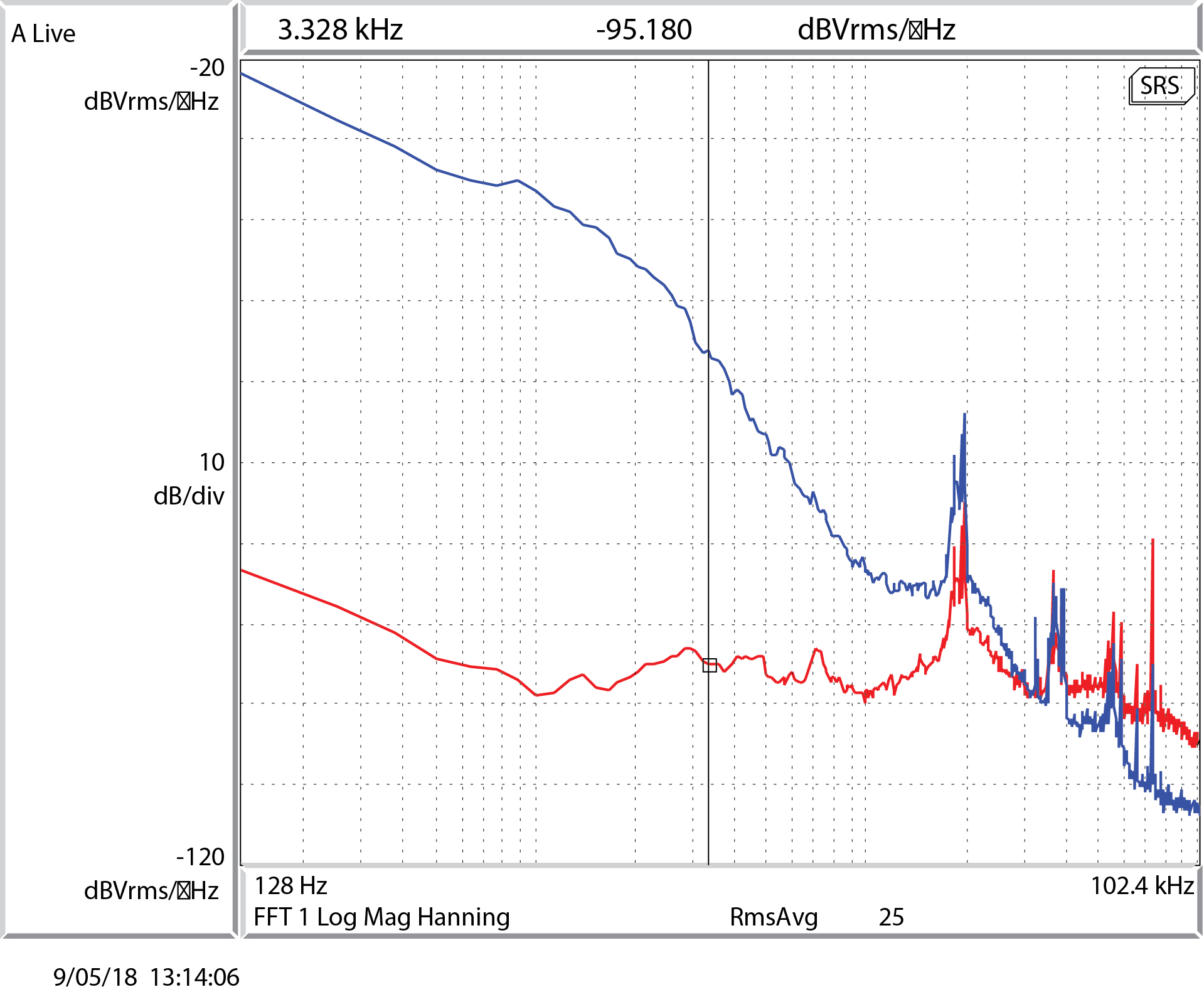
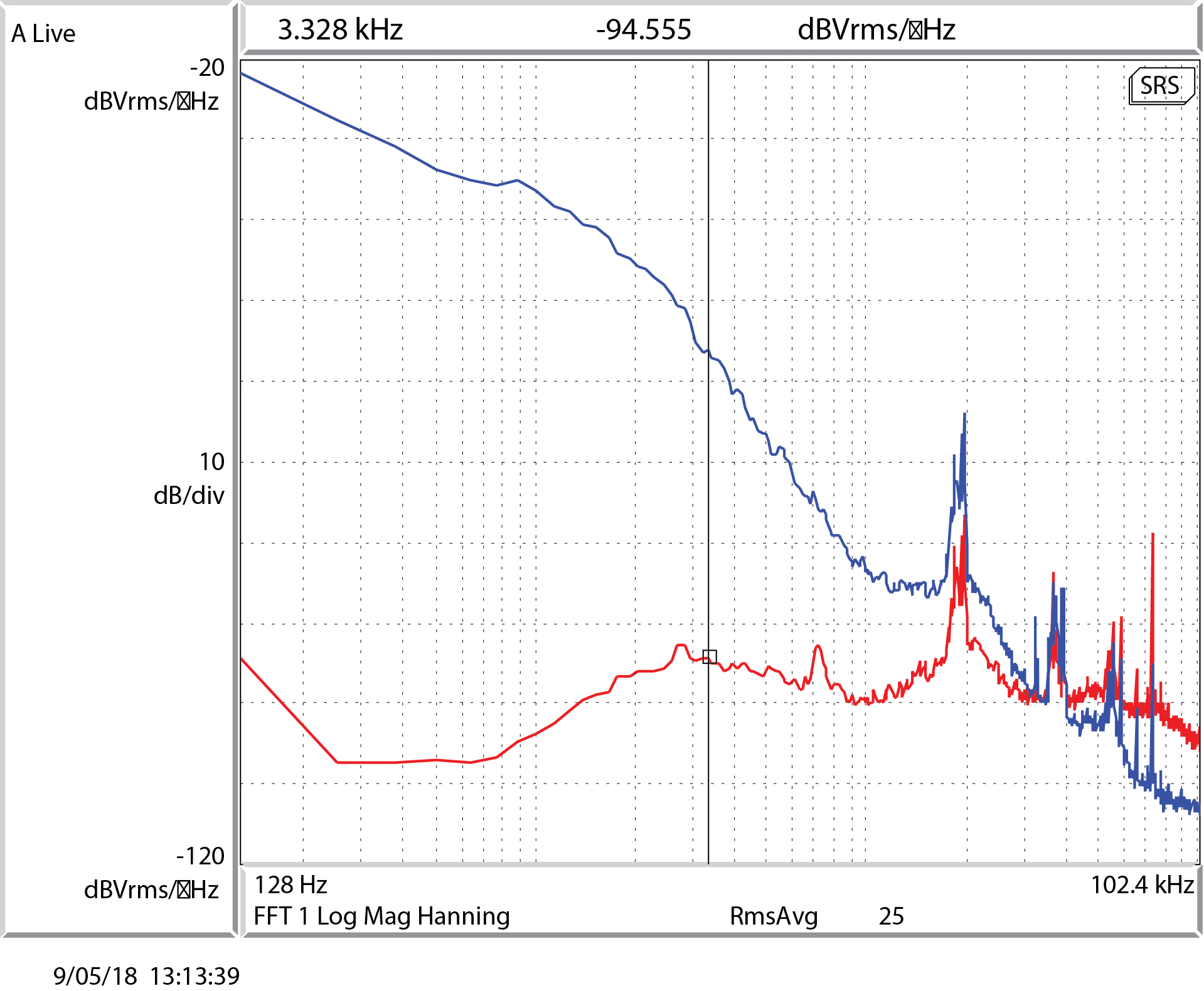
PDA.jpg and PDB.jpg show the measured power noise using photodiodes PDA and PDB respectively -
PDB was used as the in-the-loop sensor. Both show a similar degree of suppression except at low
frequencies. However it was noticed that whenever the second loop output was enabled, there was no
observed suppression with either PDA or PDB. Engaging the second loop caused the reported diffracted
power to rail at ~3.3%. I've since found out about the offset removal for the second loop (thanks Gabriele!).
Gabriele / Peter
[Peter, Gabriele]
We measured the power noise at the first loop diodes (PDA and PDB) and at the ISS second loop diodes (PDSUMINNER, PDSUMOUTER) in three different configurations
- GREEN, BROWN: first loop open, second loop open
- CYAN, PINK: first loop closed, second loop open
- RED, BLUE: first loop closed and second loop closed

There is still something not quite right, since the intensity noise is larger than expected when the ISS second loop is closed. Some comments:
- When all loops are closed, we see a quite large RIN as measured in the second loop diodes (the DC signal of the sum is about 1, so the values in the plot are close enough to RIN)
- When we close the first loop, the first loop photodiodes show the expected large suppression. However, the ISS second loop diodes flatten to a value of about 1e-6, which larger than what we normally have (that was more like 1e-7)
- When we close the second loop, both in-loop and out-of-loop diodes are suppressed below the 1e-6 level described above, and the in-loop diode shows a bit more suppression as expected. However, the first loop photodiodes are way noisier than when the second loop was off. Indeed, the level of power noise measured in the first loop diodes is consistent with an additional white noise at a level of 1e-6, common to ALL eight ISS second loop photodiodes
This behavior is puzzling: it looks like there is something injecting white power noise at a level of 1e-6/rHz in RIN, somewhere in between the ISS first loop and the ISS second loop.
Sounds familiar. 1st loop sensors don't see the intensity noise of the light coming into the IFO. I thought that it was gone with the sanitization of polarization on the PSL table 1st loop path, maybe this is a different mechanism.
Anyway, with 1st loop closed and 2nd loop open (H1:PSL-ISS_SECONDLOOP_OUTPUT_SWITCH is "OFF"), 1st attachment shows, among other things, zero coherence between ISS 1st loop out of loop sensor (PDA) and MC2 TRANS SUM, but there's a large broad coherence between the 2nd loop sensor and MC2 TRANS SUM. 2nd loop in- and out-of-loop sensors have perfect coherence with each other.
The noise of the 2nd loop board itself is somewhat significant for f<10Hz (2nd attachment, taken with 2nd loop still open but H1:PSL-ISS_SECONDLOOP_OUTPUT_SWITCH is "ON") but that doesn't negate the fact that 1st loop diodes don't see the intensity noise going into the IFO.


As Keita mentions, this is due the fact that the bow-tie PMC has no suppression of the wrong polarization, that TRANS, ISS, FSS and REFL are looking at different output ports of the PMC, and that the ports are using individual power adjustments based on a quarter waveplate and a polarizer. As a net effect, each beam looks at a different polarization state. We didn't clean this up, only mitigated the problem in the ISS path by dumping some of the power with a splitter.