stefan.ballmer@LIGO.ORG - posted 15:36, Tuesday 25 September 2018 - last comment - 08:45, Thursday 27 September 2018(44150)
ALS noise mitigated
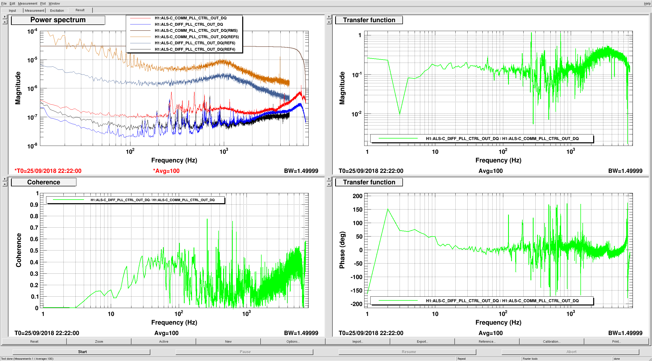
After diagnosing the ALS COMM and DIFF noise as being related to beat note slip in the COMM PLL (see alog 44140), we tried to lower the COMM and DIFF PLL gains by 20dB (from +26 to +6).  This pretty much killed the excess noise. The attached plot shows both COMM and DIFF PLL locked.

We now should have more than a factor of 10 headroom on the ETM drive.
Images attached to this report
Comments related to this report
Some may recall an issue we had back in July and August when we were testing the new green arms, where the out-of-loop X-arm frequency noise measurements we were making made little sense:

In-loop COMM Frequency Noise
IR Frequency Noise measurement using COMM as out-of-loop sensor
COMM Frequency Noise measurement using IR as out-of-loop sensor

Our out-of-loop witnesses of X-arm frequency noise disagreed by about a factor of 10: COMM frequency noise was ~2 green Hz RMS, but IR frequency noise was 12.4 red Hz RMS (~25 green Hz RMS).  They also did not show the same spectral features, leading us to believe that our out-of-loop IR measurements were not limited by X-arm noise.

After Stefan reduced the COMM and DIFF PLL gain from 26 to 6 dB, the in-loop COMM frequency noise plummeted, and we start to see some of the same spectral features as seen in alog 43214.  In-loop COMM now reports 6.7 green Hz RMS noise, which is still slightly higher than the ~2 Hz reported by our out-of-loop IR witness in August.  Could be worth it to try an reduce the gain further, then redo this measurement.

Also plotted is the ETMX coil master monitor now as opposed to this morning.  ETMX actuation is greatly reduced.

Questions remaining: It doesn't make sense that the in-loop sensor would see higher noise than the out-of-loop sensor, particularly when we have proof that the COMM PLL was actuating hard on ETMX.  Could be that COMM and DIFF PLL CTRL OUT are calibrated incorrectly, further investigation required.
Images attached to this comment

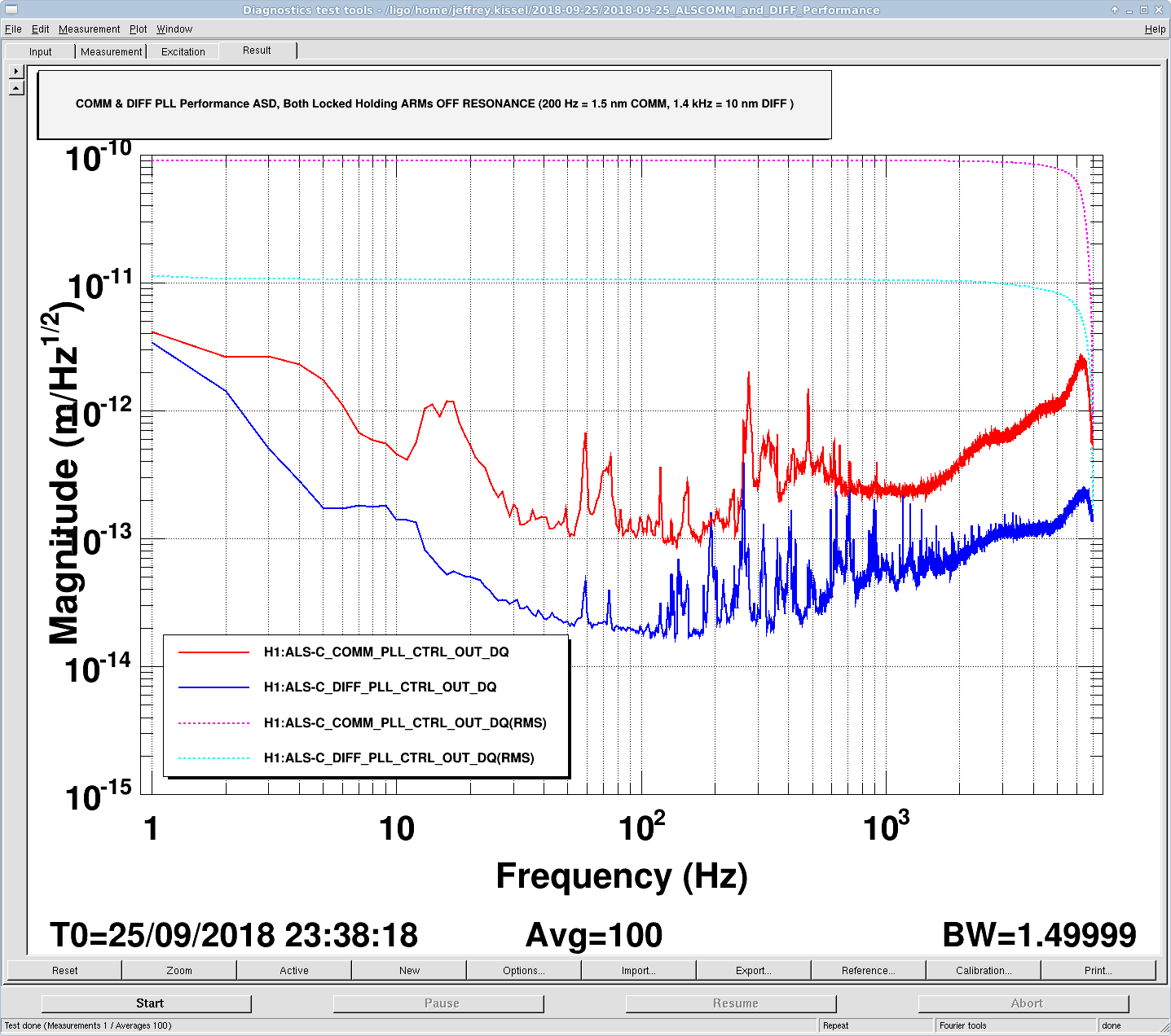
Here's a plot of ALS COMM and ALS DIFF control signals (H1:ALS-C_COMM_PLL_CTRL_OUT_DQ and H1:ALS-C_DIFF_PLL_CTRL_OUT_DQ that come "pre-calibrated" into um) when they have the arm cavities under control, holding with a 200 Hz and 1.4 kHz detuning offsets in place, respectively, later in the day during IFO lock acquisition. Assuming a conversion from frequency to length using the green wavelength, that's an offset of COMM 200 Hz * L_arm* lambda_g / c = 200 Hz * 4000 * 532e-9 / 3e8 = 1.42e-9 m = 1.4 nm. DIFF 1481 ct * (0.11802 ct / Hz)^-1 = 12549 Hz 12549 Hz * L_arm* lambda_g / c = 12549 Hz * 4000 * 532e-9 / 3e8 = 8.9e-8 m = 90 nm. The COMM offset comes from H1:ALS-C_COMM_VCO_CONTROLS_SETFREQUENCYOFFSET on the COMM VCO (pre-calibrated into Hz), and the DIFF offset comes from the H1:ALS-C_DIFF_PLL_CTRL_OFFSET, which is uncalibrated ADC counts. EDIT as a result of Daniel's comment (LHO aLOG 44163) below P.S. now that I've found Kiwamu's LHO aLOG 20629, and compared it against the calibration filters installed in the PLL_CTRL filter bankI'm skeptical that the filters are correct. - Kiwamu measures 0.11802 ct / Hz. - The filters have gains of "cnts2V" = 3.05176e-4 V/ct and "V2Hz" = 1.90146e4 Hz/V whose product is 5.8028ct / HzHz / ct. Which makes the inverse 0.1723 ct / Hz.Thus the "pre-calibrated" ASD of the performance as reported by the DIFF PLL CTRL may in fact be too high by a factor of 6.Thus the percent difference is 100*abs(0.11802 - 0.1723)/0.11802 = 45.9% So, to correct the calibration of the H1:ALS-C_DIFF_PLL_CTRL_OUT_DQ channel, one must multiply by 0.11802 ct / Hz ---------------- = 0.68497 [Hz / "Hz"] (or [m / "m"] assuming the conversion from frequency to displacement is correct). 0.1723 ct / "Hz" The calibration is off by a "about a factor of 2" (not the factor of 6 as mentioned in the striken comment). One area of suspicion that would resolve the remaining discrepancy: "cnts2V" is 3.05176e-4 V/ct which is equivalent to 20 V / 2^16 ct. The LIGO-standard differential input 16 bit ADCs have a calibration of 40 Vpp / 2^16 ct = 6.1035e-4 V/ct, as demonstrated in T1100538. If "cnts2V" were changed to match that value, the product would be 6.1035e-4 V/ct * 1.90146e4 Hz/V = 11.606 Hz / ct, and the inverse = 0.086166 ct / Hz. That reduces the percent difference to 100*abs(0.11802 - 0.086166)/ 0.11802 = 26.9% and reduces the correction factor to 0.11802 / 0.086166 = 1.3697.
Images attached to this comment
Non-image files attached to this comment

Isn't it the inverse?
"cnts2V" = 3.05176e-4 and "V2Hz" = 1.90146e4 whose product is 5.8028 Hz / ct => 0.17 ct/Hz.
A tuning of ~20kHz/V is about what we expect the VCO w/ FDD calibration to be, when we measure at the single-ended output of the CM board. However, the DAQ readback implements a differential driver that adds a gain of 2, therefore the 3.05176e-4 V/ct is relative to the CM board output. Does the VCO filter has a gain of 1 at DC?