I spent the last 1.5 hour trying to get through the initial green alignment. But the X green is broken in (at least) two ways
- There are intermittent, but frequent periods of high noise and glitches, as already reported in the past. It's impossible to keep the X arm locked in stable way for more than a couple of minutes. It's time to check what's wrong with the X end laser.
- Even when the arm is locked on green, engaging the WFS fails. It seems to me that DOF1_P and DOF1_Y have both wrong signs, but I was not able to do much testing because of the glitches
Tried to check that the Xarm and Yarm WFS have similar sensing matrices. All ASC loops on green arms open. Step ETMX in PIT, see on both WFS A and WFS B. Step TMSX in PIT, see on WFS A, very small on WFS B.
Step ETMY in PIT, see on both WFS A and WFS B. Step TMSY in PIT, see on WFS B, not at all on WFS A. This is how things should be, with the current sensing matrix.
For the Xarm, if WFS B is being used as the sensor for TMS, but the sensor doesn't respond to TMS motion, its not surprising that we're struggling to use the Xarm WFS.
We tried (as Hang writes) to make the Xarm analog gain and whitening settings the same as Yarm, but that did not help. So, we left them as they were. See screenshot for current settings for each arm.
Gabriele is measuring the sensing matrices for the green WFS more carefully.
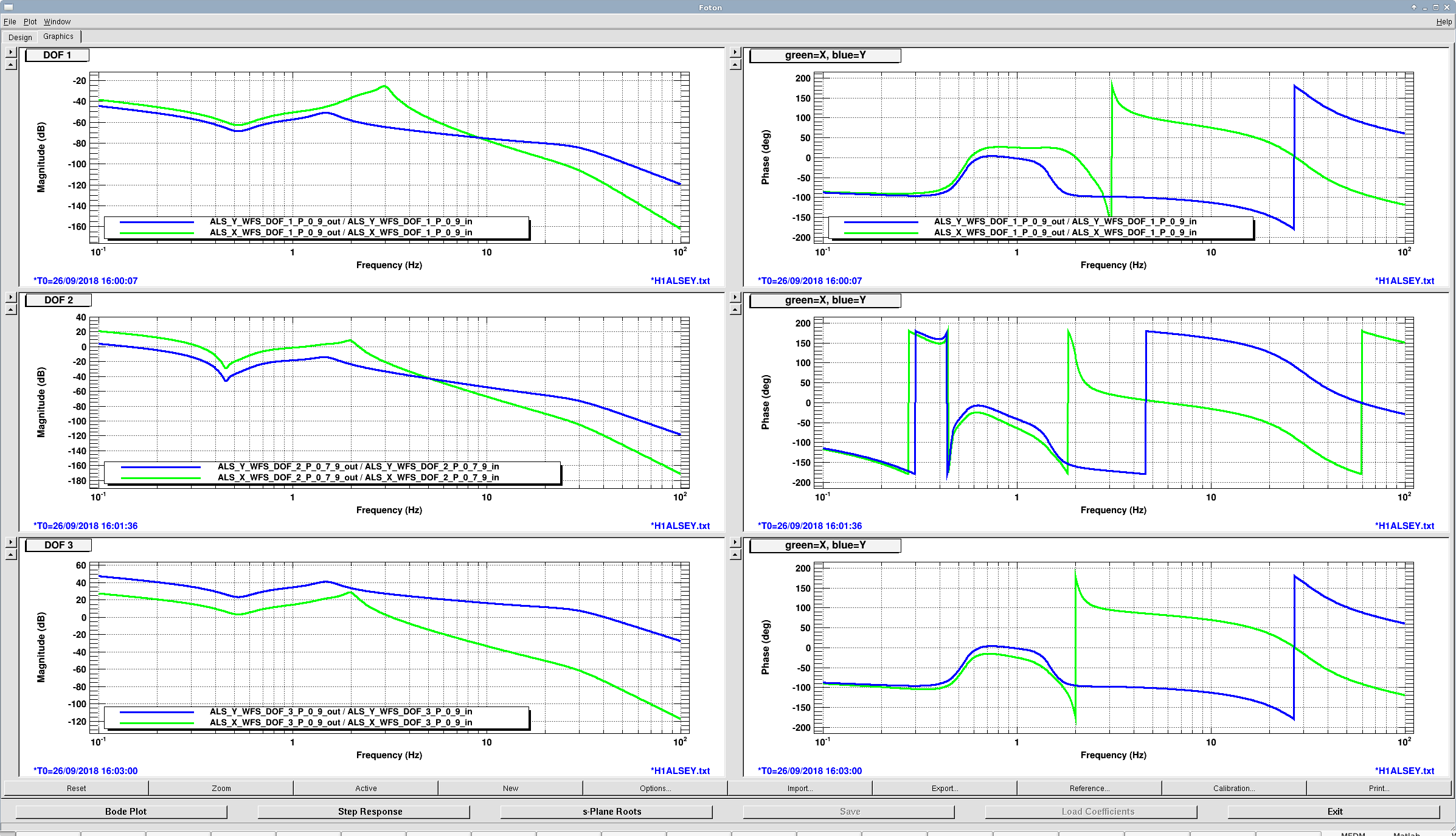
Also, I plotted the control filters for both arms' ASC loops. The shapes down near the UGFs (~0.1 Hz) are the same with some DC gain differences. The lowpasses are very different from eachother though. The Xarm filters have more aggressive lowpassing (6th order), but Hang had empirically found in the past that the Yarm couldn't handle that, so it has only 4th order lowpasses. To make the phase okay near the control band, the cutoff frequencies for the lowpasses are different.
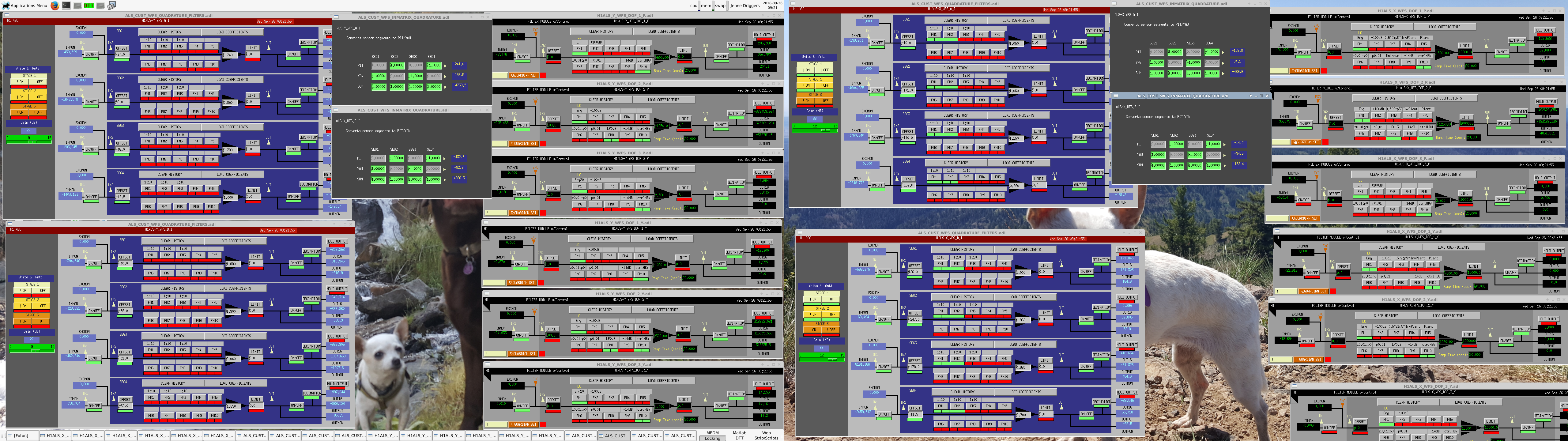
We noticed that the low-pass filters (corner freq at 0.3 Hz; FM10) in the ALS_X/Y_WFS_A/B_I_PIT/YAW filter banks were turned on. However, the design should not have those filters on. This could explain in part the green WFS oscillation as an extra LP at 0.3 Hz would for sure degrade the phase margin at the designed UGF of ~ 0.1 Hz.
Now we turned all the LPs off.
In addition we noticed that the X arm green WFSs had two stages of whitening while the Y arm has no whitening. Nonetheless, this was consistent with the settings in the past when the green WFS worked properly. Thus for now we leave the whitening setting as it is.
Xarm FIBR trans is much noisier than Yarm.
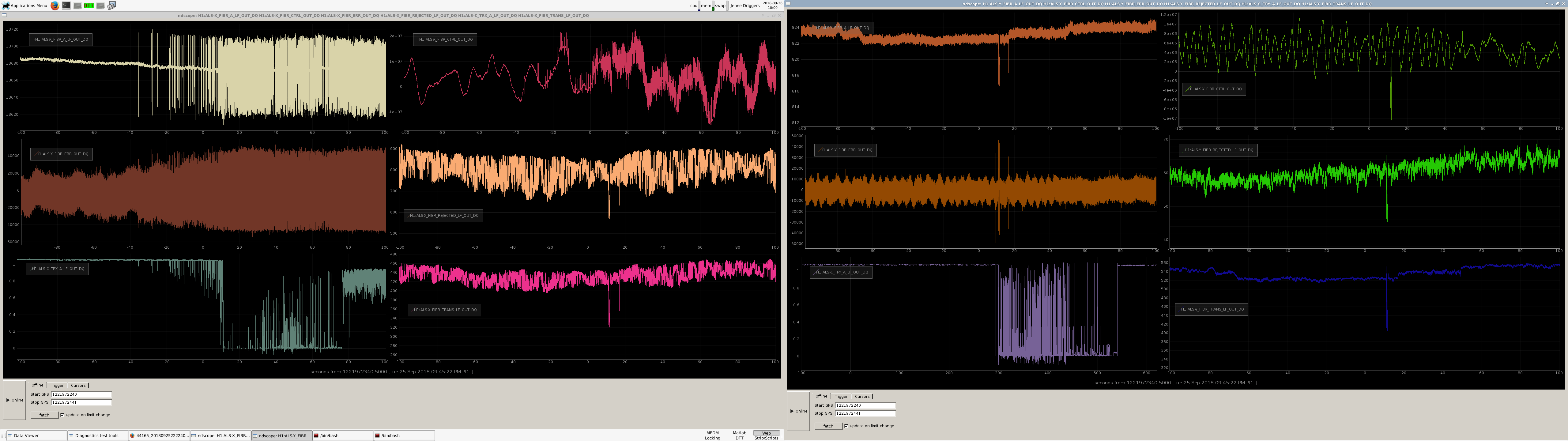
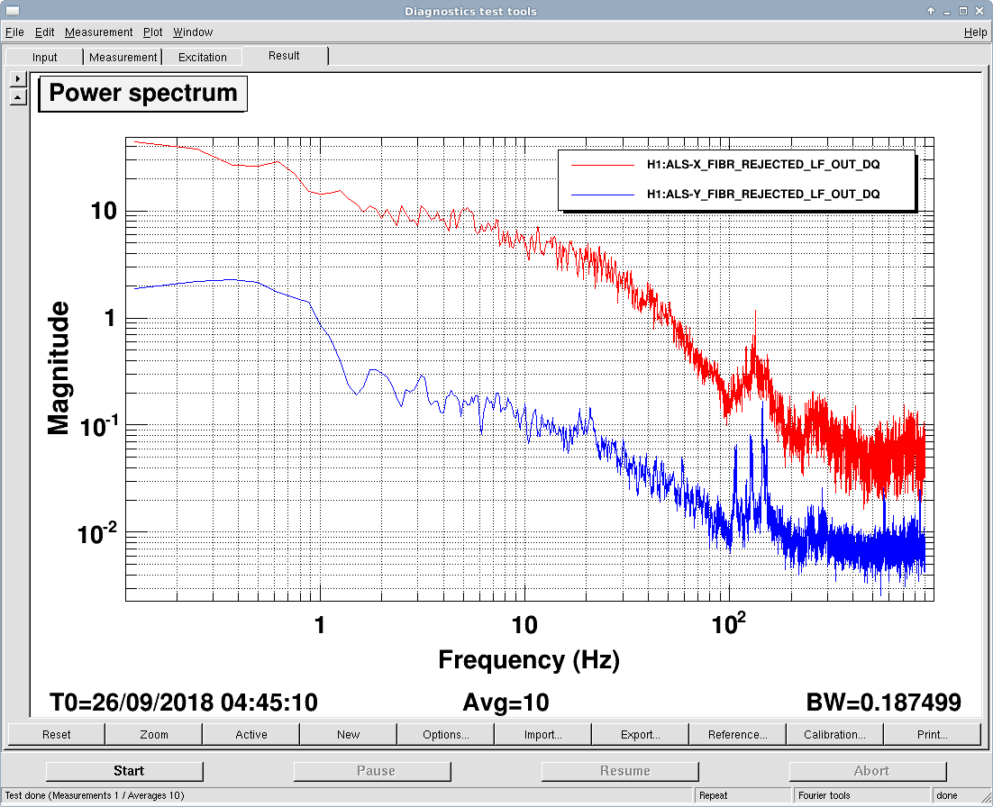
Attached is a time series showing a time from last night that Craig referenced (alog 44165) when Xarm starts clean, and gets glitchy. Left panel is all things Xarm, right is all things Yarm. Also attached is a spectrum.
In the Xarm time series, you can see that the FIBR_A_LF_OUT sees glitches at the same time as the ALS-C_TRX. You can also see that the FIBR_CTRL is outputting glitches at the same time, in response. The FIBR_A_LF is telling us about the phase difference between the light coming down the fiber from the PSL, and the end laser. So, it's not telling us which of those things has a problem, but Daniel's hunch is that something is causing the fiber to vibrate or shake. Note however that the FIBR_TRANS and FIBR_REJECTED signals are bad for X throughout the whole time series shown, not just the times that we're seeing glitches.
The spectra show us that yes, the Xarm is more noisy than Y, but there isn't one particular characteristic frequency that we can blame.
Created corresponding ticket FRS Ticket 11535.
A few more notes / things I learned this morning:
ALS-X_FIBR_ERR_OUT_DQ is the error signal for the end station PLL. When it hits its limit we see a glitch in FIBR_A_LF_OUT. But, the ERR_OUT monitor channel has a factor of 10 on the board for the monitor, so the actual signal voltage used isn't that high. But maybe it is still too much for something.
Increasing the gain on the FIBR_PLL board makes the glitches not as apparent in green trans. But we still see them in ERR and A_LF. Right now, we're using the boost in the FAST path of the Xarm FIBR_PLL common mode board to give us this extra gain. Since we can suppress away the glitches by actuating on the laser, maybe that indicates that the problem is with the laser. But, the glitches seem kind of similar to what we saw when we had the tag flicking in the AC breeze hitting the fibers in the MSR, which was an issue with the signal coming down the fiber.
I am concerned that we are saturating something in the readout chain of the broadband PD. According to the screen for ALS-X_FIBR_A_DC, we have 10x as much gain on this PD than on the Yarm. I see this in that the FIBR_A_DC_TRANSIMPEDANCE channel on Xarm is 10x larger than the one on the Yarm. Is this correct?
For much of the day, since we were mostly able to stay locked and hand of the IFO to IR control, we ignored this. Georgia and Craig are continuing investigations in parallel with locking.
[Craig Keita Georgia]
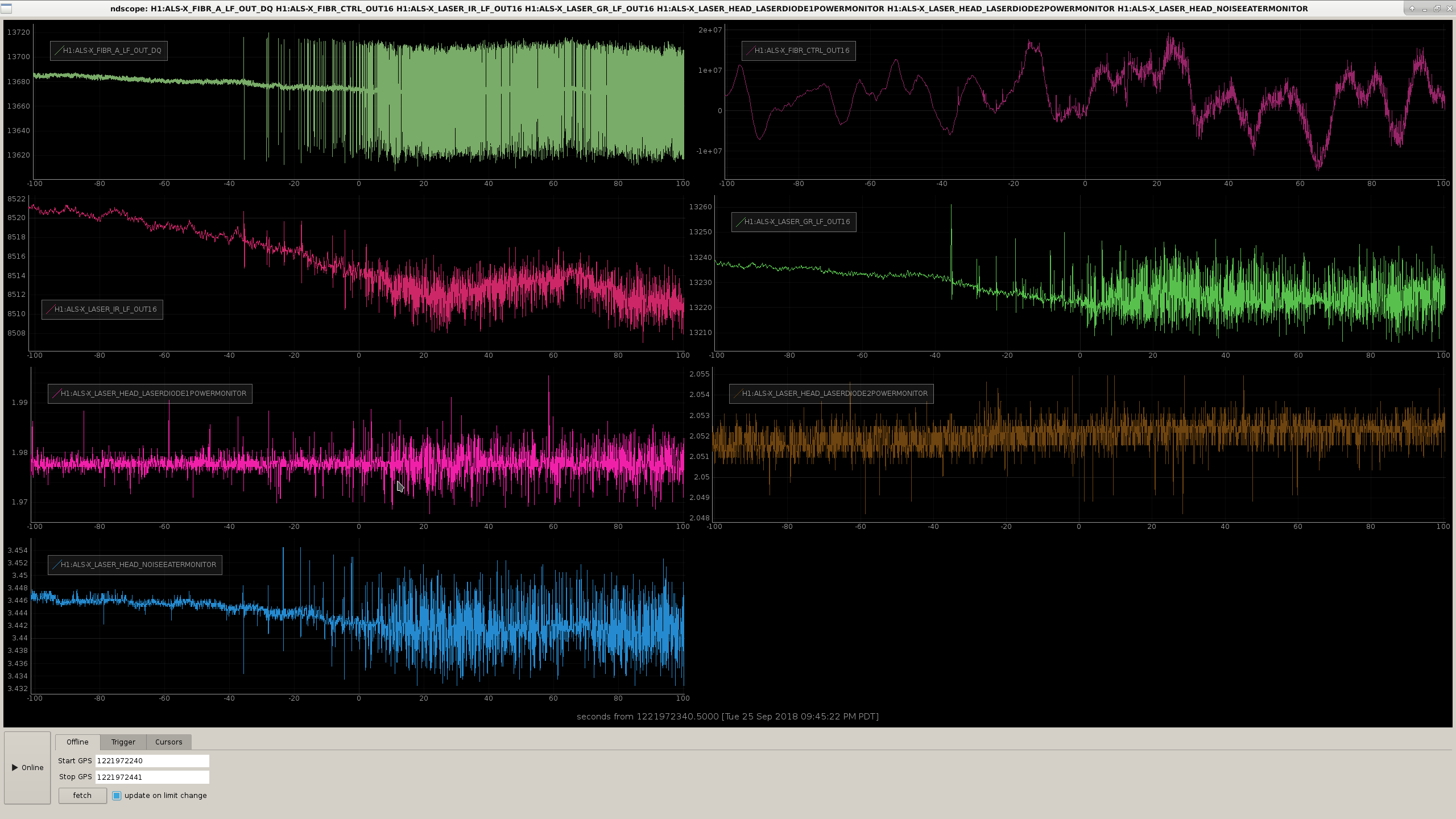
As Craig mentioned yesterday the ALS X arm noisy periods also correspond to additional intensity noise from the Aux laser at the end station. I suspect this could be the laser diode or the noise eater.
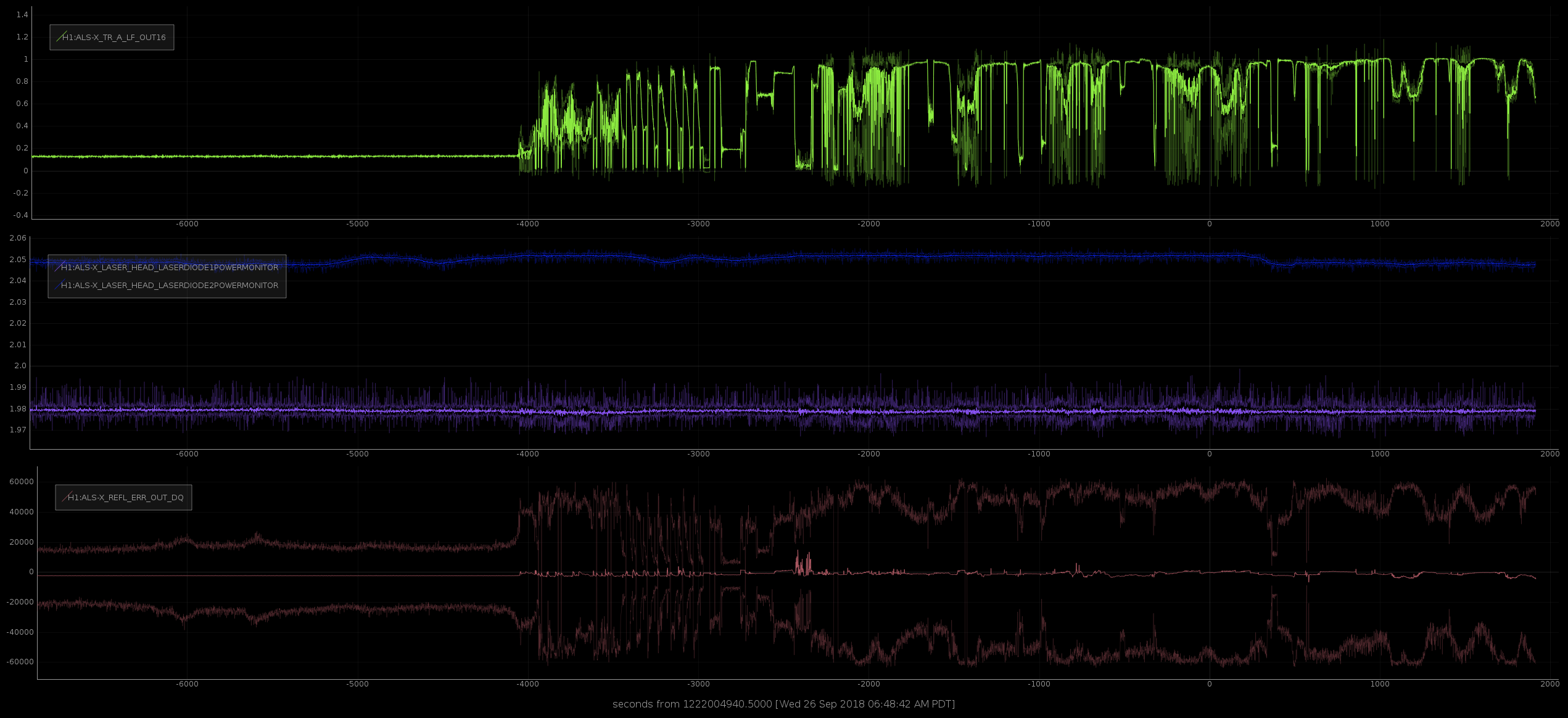
Attached screenshot shows the laser power IR and green monitors (row 2), laser diode current monitors [Amps] (row 3), and the noise eater monitor (row 4), during the noisy period from last night. I'm not sure fiber noise could cause this, but rather the extra laser intensity noise could be the source of the problems.
When we get a chance I'd like to go to the end station and change the set point current by ~100 mA and see if that changes things; perhaps we're in a bad region for laser diode 1, where the extra noise is just visible.