The X arm glitches stopped at about 8:30 am, so we could try to solve the second problem, which is that the X arm green WFS loop were not doing any good. A quick investigation showed that the response of WFS A and WFS B to ETM and TMS is different in the X arm than in Y arm. We could not quite understand why, but we decided to accept the signals as they are, measure a sensing matrix and invert it.
I measured the WFS sensing matrix at DC for both X and Y arms, by moving ETM and TMS by 0.3 slider steps in both pitch and Y. Results are below (in units of WFS/slider)
| X arm | ETM pitch | TMS pitch |
|---|---|---|
| WFS A | -2150 | 1900 |
| WFS B | 2200 | 990 |
| Y arm | ETM pitch | TMS pitch |
|---|---|---|
| WFS A | -8400 | 0 |
| WFS B | -1900 | 4000 |
| X arm | ETM yaw | TMS yaw |
|---|---|---|
| WFS A | -3500 | -200 |
| WFS B | -3300 | -1150 |
| Y arm | ETM yaw | TMS yaw |
|---|---|---|
| WFS A | 18400 | -200 |
| WFS B | -5200 | -4080 |
The sensing matrices are quite different in the two arms. We decided to push forward, invert them, and plug them in. The new sensing matrixes and the loop configuration that is currently working with the initial alignment are shown in the screenshot below. With those new values the DOF1 and DOF2 pitch / yaw error signals should all have comparable gains in terms of the ETM and TMS motions. I did not tune not look at the control filters or control gains.
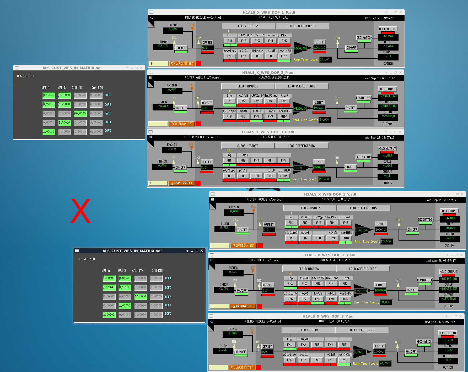
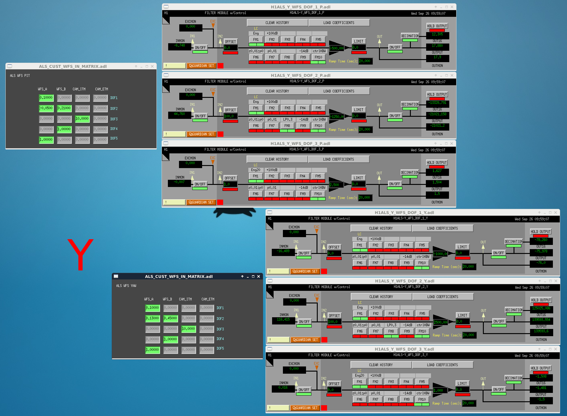
Note: increasing the yaw gain of the X arm by a factor of two made the loop unstable...