
We suspect that there might be a sign issue in the CSOFT input matrix.
We noticed this as we performed a sensing matrix measurements for CH/CS in pitch. Specifically, we dithered CH/CS in pitch at 23 Hz and measured the responses in the 4 trans QPDs. The result is the following:
| (arb. unit) | TR_X_A | TR_X_B | TR_Y_A | TR_Y_B |
| CH_P | 2.47 | 2.38 | 2.25 | 0.12 |
| CS_P | 1.52 | 2.09 | 0? | 2.22 |
On the other hand, the original input matrix for CS P was (-0.619*XA + 0.317*XB - 0.333*YA + 0.161*YB). If we plugged in the response matrix, we would end up with some thing like (-0.28 X + 0.35 Y)... This seemed to be an input signal for DS instead of CS.
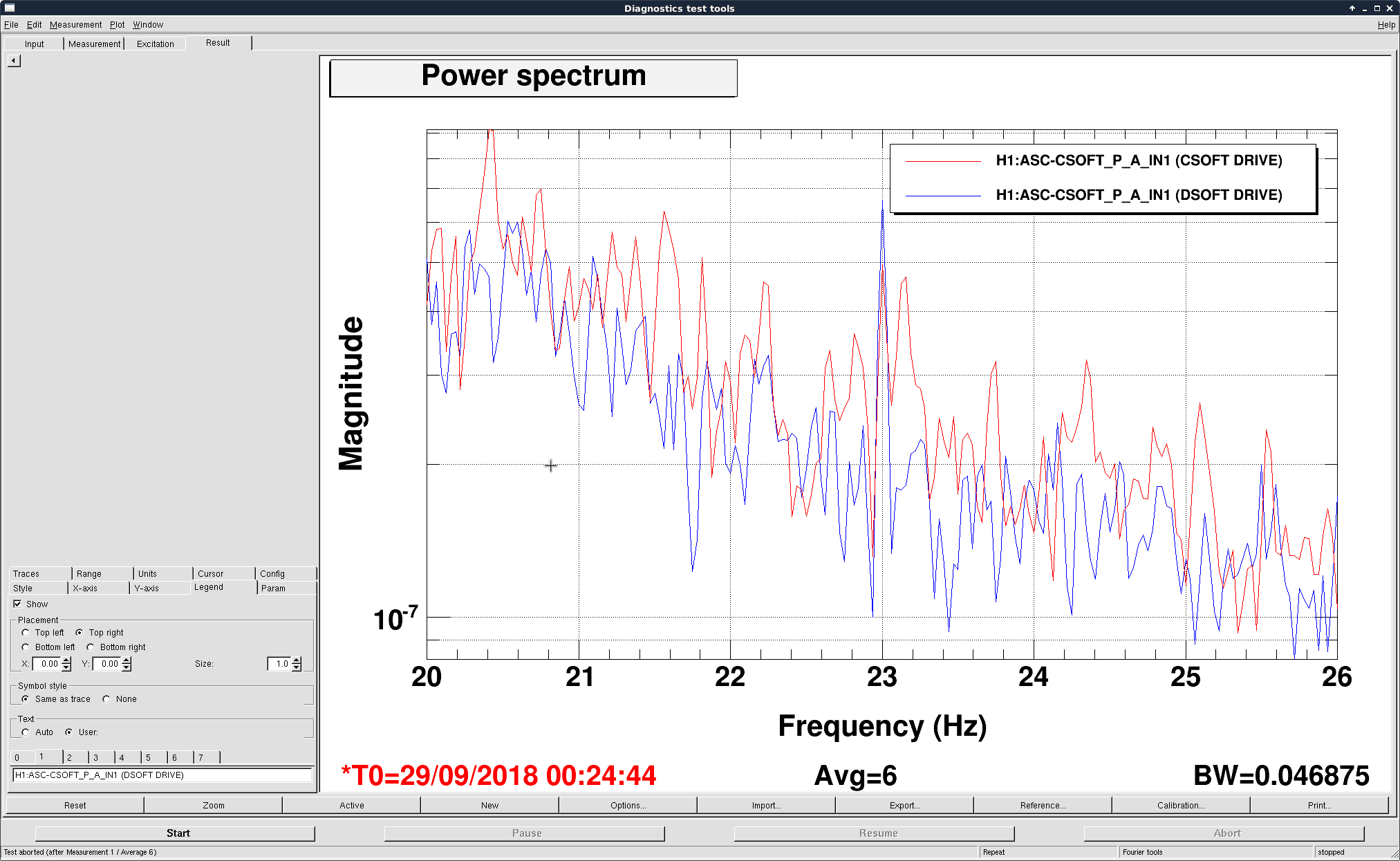
To verify this we dithered both CS and DS at 23 Hz and measured the spectra at the CS error point using the original input matrix. The result is attached in the first image. The SNR was not good yet it suggested that the CS responded more to DS drive than CS drive... Further verification is needed.
For now, we flipped the signs for the TRY signals for CS in P. I.e., we use (+0.333* YA - 0.161 * YB). We can re-engage the CS P loop with this settings fine.
=======================================================================
From the sensing matrix we also designed a super-signal for CS. We use the original CS P signal (with TRY sign flipped in the input matrix) as the low freq signal; it sets the DC pointing of the CS P loop and was designed to be decoupled from TMS motion. unfortunately, this combination of TR QPDs makes the CS almost degenerate with CH, which seemed to a caused non-minimum phase delay in the measured CS P OLTF. Thus for the high-freq component, we used the combination of the TR QPDs that are decoupled from CH P. Since this signal is AC coupled, it does not need to be insensitive to the TMS whose drift was at ~ hour timescale. The blending frequency was currently set to 0.06 Hz.
The input matrix for CS P thus reads as
| TR_X_A | TR_X_B | TR_Y_A | TR_Y_B | |
| -0.619 | +0.317 | +0.333 | -0.161 | CS_P (<0.06 Hz) |
| 0.42 | -0.44 | 0 | -0.13 | CS_P (>0.06 Hz) |
The overall scale for the HF component was set to match to the original, LF signal. For this blended signal, we could close the CS loop stably yet we could not engage the FM3 integrator (zero at 0.1 Hz and pole at 0 Hz). This might be due to the imperfect gain matching of the LF/HF signals. Also the HF was tuned to be X = Y, whereas the original signal seemed to have a stronger response to Y than X. However we have not repeated the measurement at other frequencies to verify the signal strength. This is something needs further investigation.
Nonetheless, the boost starting from 0.1 Hz should not have too much an impact at ~ 0.5-0.6 Hz where we need to damp the dP_dTh instability. As the new setting allows us better decouple the CH signals, we could increase the overall loop gain to 30 (originally was 6). Not turning it on might also help ensure the gain hierarchy between CS and CH at LF (is that necessary though?).
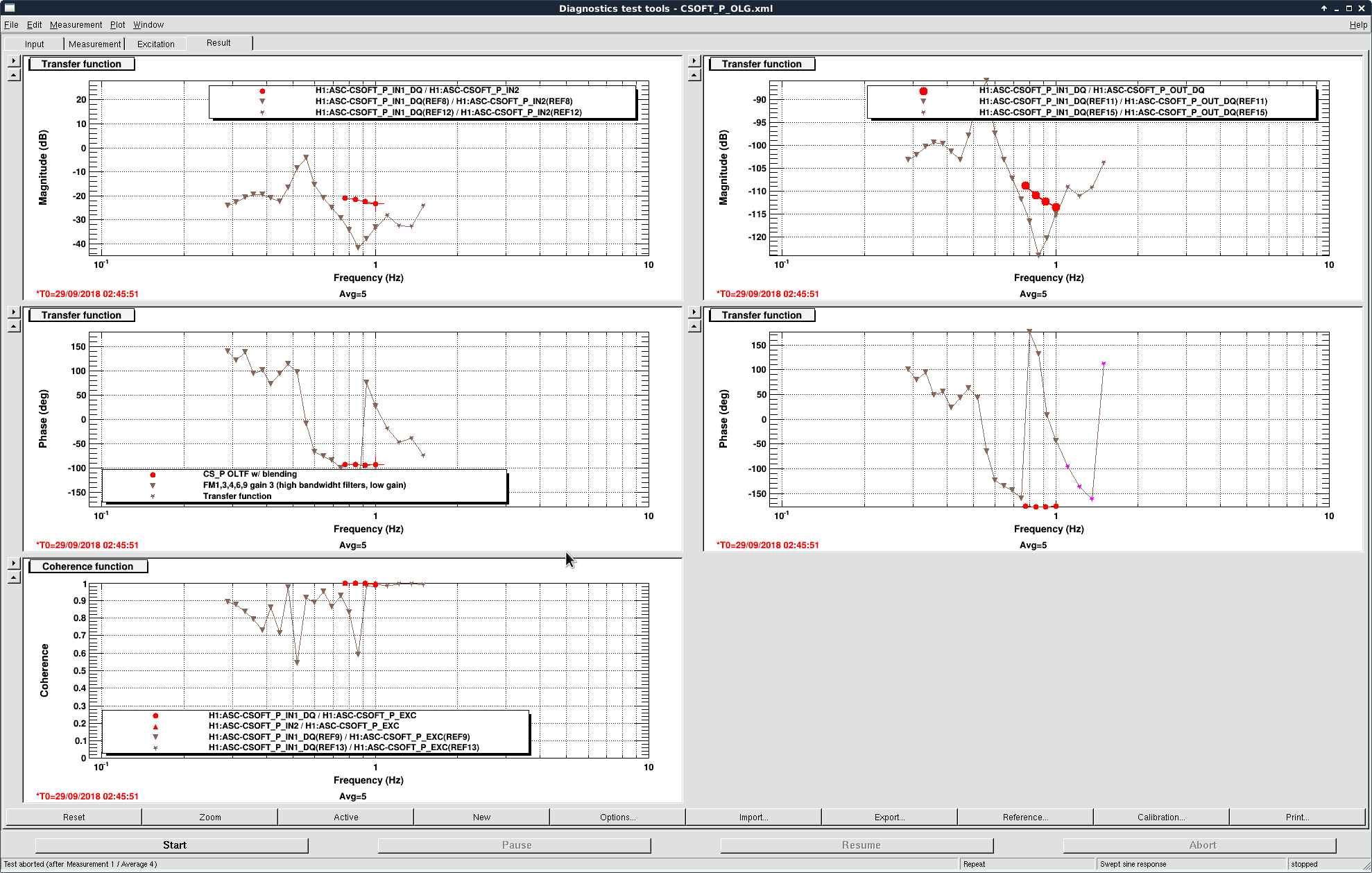
We also measured the CS P OLTF using this super sensor. The result is shown in the second plot. Here the red traces was response with the new signal. There seemed to be no right-hand zeros around ~ 0.8 Hz, as a result of better decoupled input sensing.
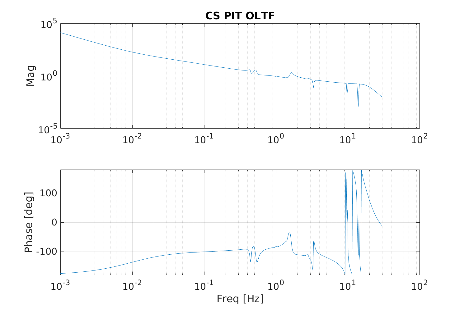
As a reference, we also show the CS OLTF model in the third plot. The overall gain was set arbitrarily. Also I was using a default quad SUS model which did not exactly match the real LHO quad resonances (which leads to the non-smooth features at 0.5 Hz and 1.5 Hz). Nonetheless the phase behavior at ~ 1 Hz where we measured seemed to be consistent with the model.
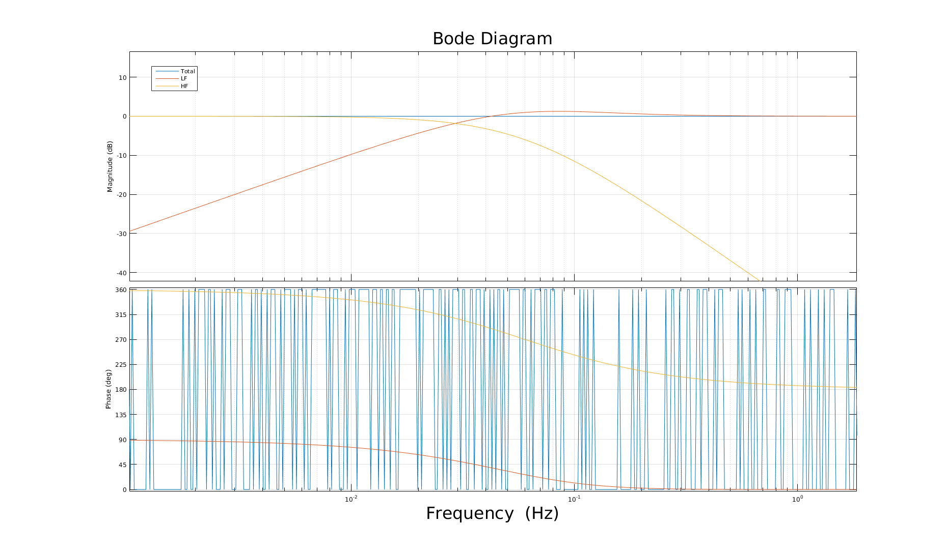
Lastly we show the blending filter in the last figure.
=======================================================================
I only tested pitch for now and thus did not put the blending desgin into the guardian. The only modification I made was to change the input matrix for the original CS_P input matrix.
To repeat the test I did, please use the original guardian to engage the soft loops and then turn off the FM3 in CS P. Then open the CS loop and go to the CS blending screen to turn on the blending filters (both FM5s in CSOFT_P_A/B) as well as CS_P_B input and gain (= 1) to enable super sensor. Then re-engage the CS P loop. I was able to increase the DC gain to 30. However, I tried to further increase it to 100 but it caused a lockloss. It might be due to that I did not carefully match the LF/HF gains and caused some un-modeled features.
Actually, the matlab model ( negative feedback) and dtt measurement (positive feedback) should differ by 180 deg in phase, whereas in the plots they had the same sign. Thus I might messed up the sign of the HF signal...
Nevertheless, the measurement at around 1 Hz at least showed no weird features from cross coupling. Thus the errors blending scheme stills seems promising for enabling the high BW soft loop ctrl.