We tested again the digital compensation of the Sidles-Sigg torque at 10 W.
========================================================
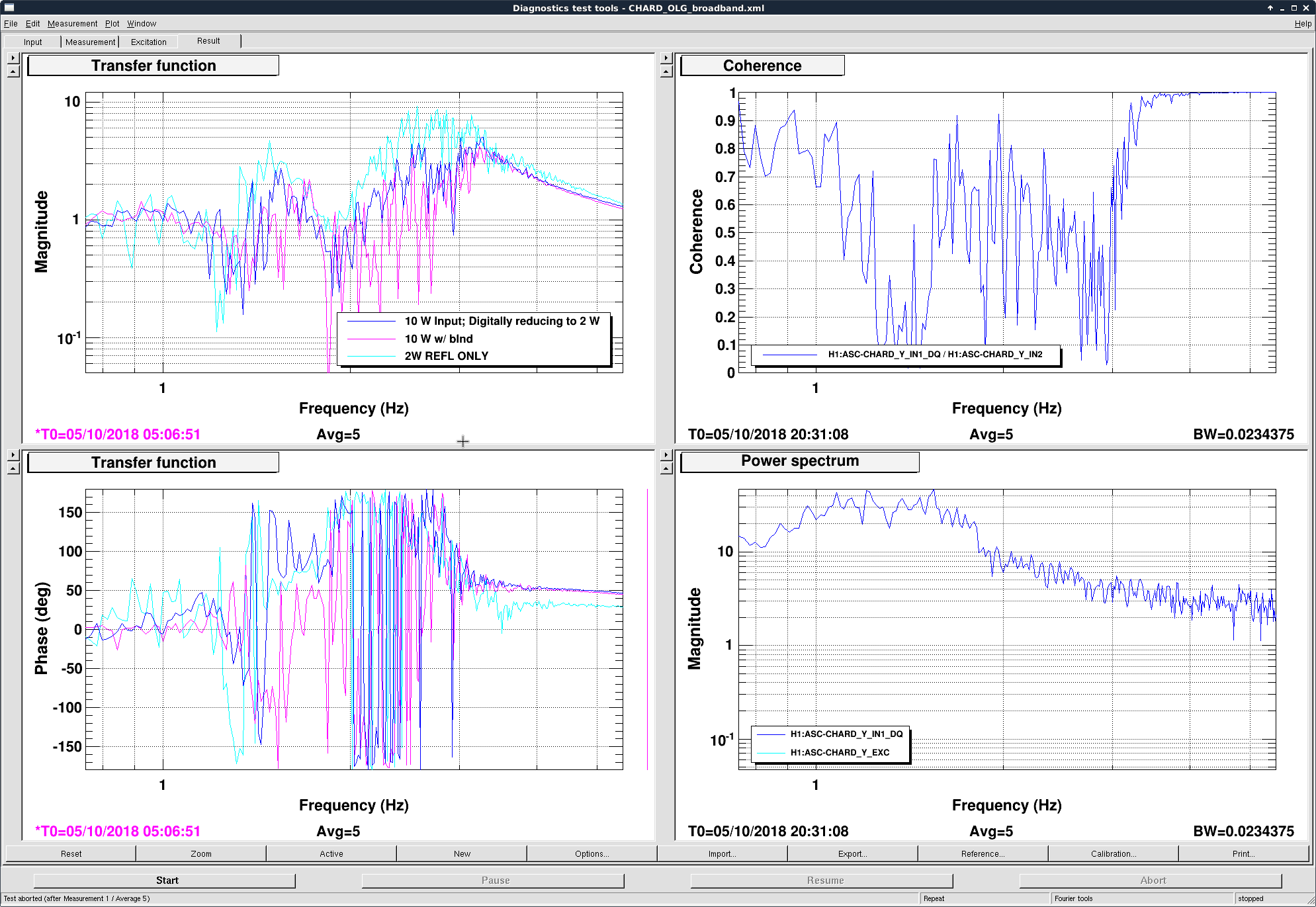
For yaw the subtraction was pretty successful. Please see the first attached image.
The cyan trace is the DHARD YAW OLTF measured at 2 W.
The pink is the OLTF measured at 10 W without any digital subtraction. We can see the OLTF changes as the radiation torque modifies the plant.
Lastly the blue is the OLTF for DHARD YAW still measured at 10 W, but this time with a digital path to create a torque canceling the radiation torque from the Sidles-Sigg effect. It successfully reduced the OLTF to look like the 2 W one. The gain for the subtraction at 10 W is -0.8, and we expect it to scale roughly linearly with respect to the arm circulating power.
========================================================
Although yaw was successful, pitch was not. As we tune the gain for the subtraction path we saw in the DHARD PIT error peak a peak showing up at ~ 0.8 Hz or so, consistent with the main resonance frequency shifted by the radiation pressure. The same peak did not show up if we did not turning on the compensation, indicating it should be suppressed by the ctrl loop. Thus we suspect the original of the peak was due to I poorly measured the sus plant and the fitted main resonance peak was slightly off compared to the real one. As we subtract two resonant peaks with slightly shifted frequencies, we created a sharp zero in the OLTF. The peak then caused strong gain peaking in the closed loop system.
The solution is therefore to take a more careful measurement of both the L2 torque to L3 pitch, and the L3 torque to L3 pitch suspension plants.
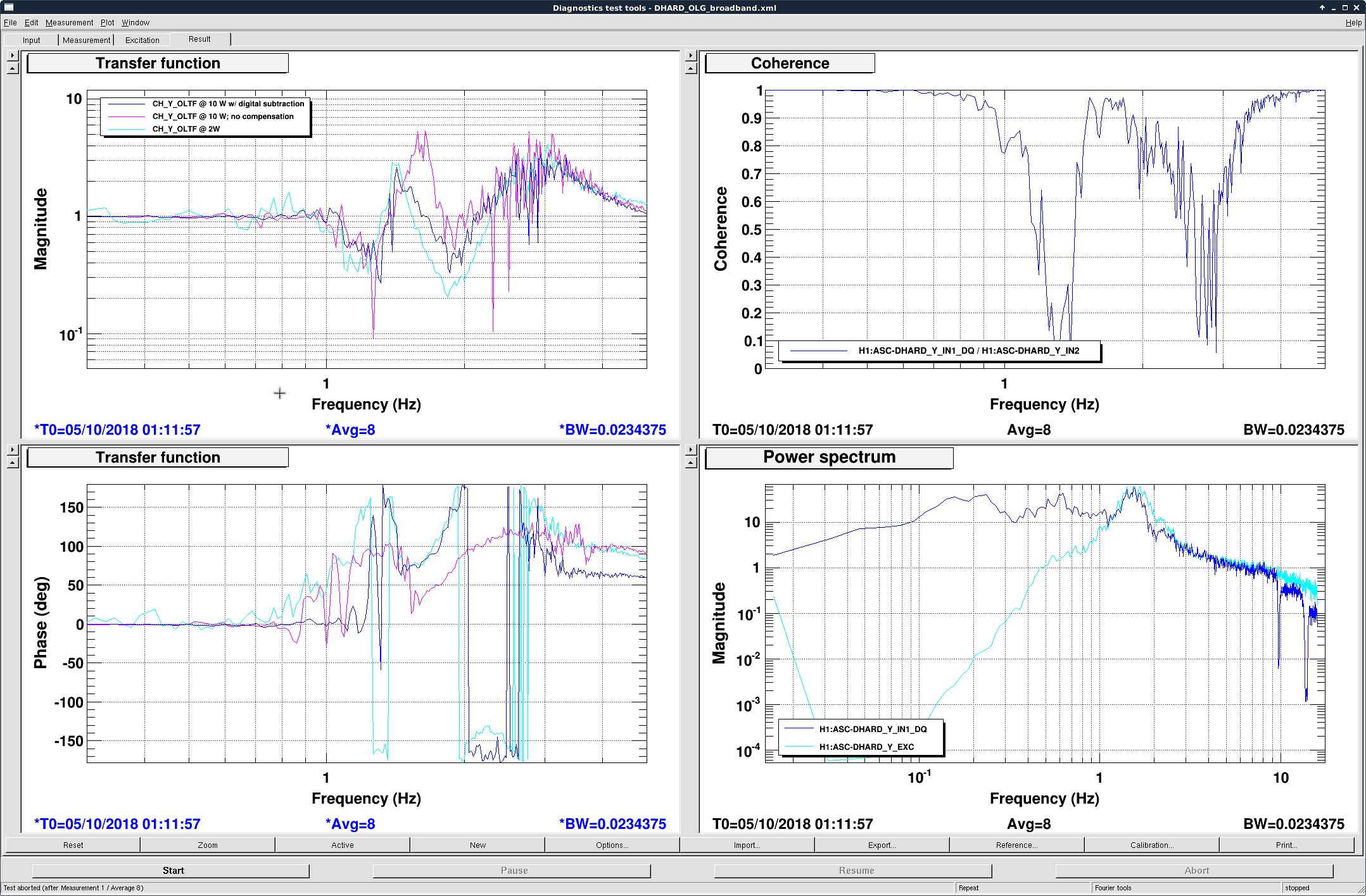
Attached is the similar plot for CHARD YAW. Due to the fast lock losses we could not get more averages to clean up the plot, yet it seemed that the compensation is making the CHARD YAW OLTF closer to the 2W one. Maybe we are a bit under compensating, but as we are creating a digital soft mode (which by itself destabilizes the loop) to cancel the hard mode, it is safer to under subtracting then over subtracting.
The error signal we used is the same blended CHARD YAW error signal as currently used in the regular ASC ctrl loop. As above 0.4 Hz the error signal is essentially from the TR QPDs, which are clean signals sensitive only to the ARM DOFs but not the corner ones, we should expect it work as good as DHARD. The ASC-RPC_CHARD_Y_GAIN used for this plot is +0.8 and should scale roughly linearly with input power. I.e., roughly the gain should be +0.8 * (input power / 10 W), though we still need some fine-tuning as the optical response (which we need to calibrate the cts input back to physical CHARD radians) may change wrt the input power.