Summary
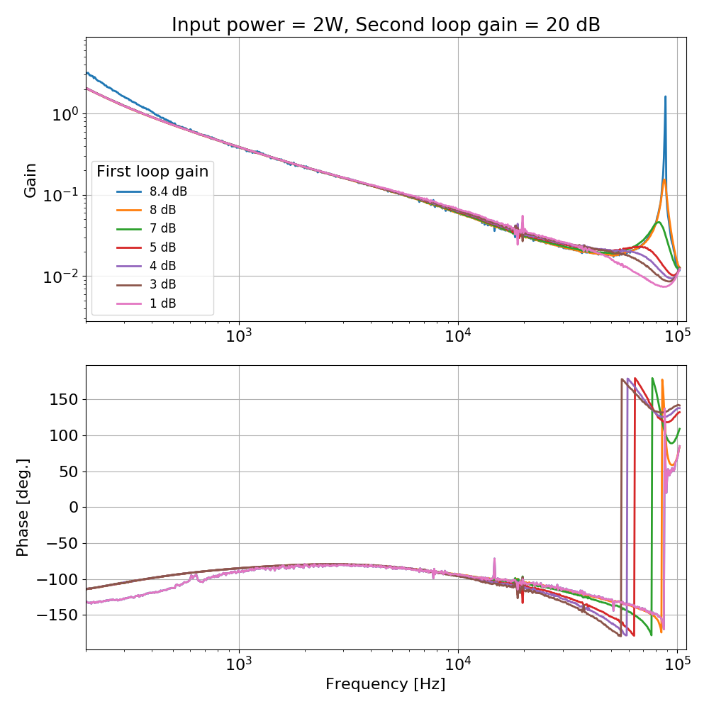
In brief, the ISS second loop could not be engaged because the gain of the FIRST loop was too high, resulting in a large gain peaking at 88 kHz, which made the ISS second loop unstable for high gain or high power. Indeed, the gain of the first loop was 8 db: increasing the gain to 8.6 dB made the FIRST loop unstable even without the second loop. I reduced the gain to 4 dB and now the ISS second loop transfer function looks ok. I could engage the second loop at 2 W with AC coupling, increase the power to 25 W, DC-couple the second loop and engage three boosts.
I tested once the following procedure
- go to 2 W input power
- request ISS_ON in the IMC guardian
- go to 25 W
- request ISS_DC_COUPLED, which engages the first two boosts
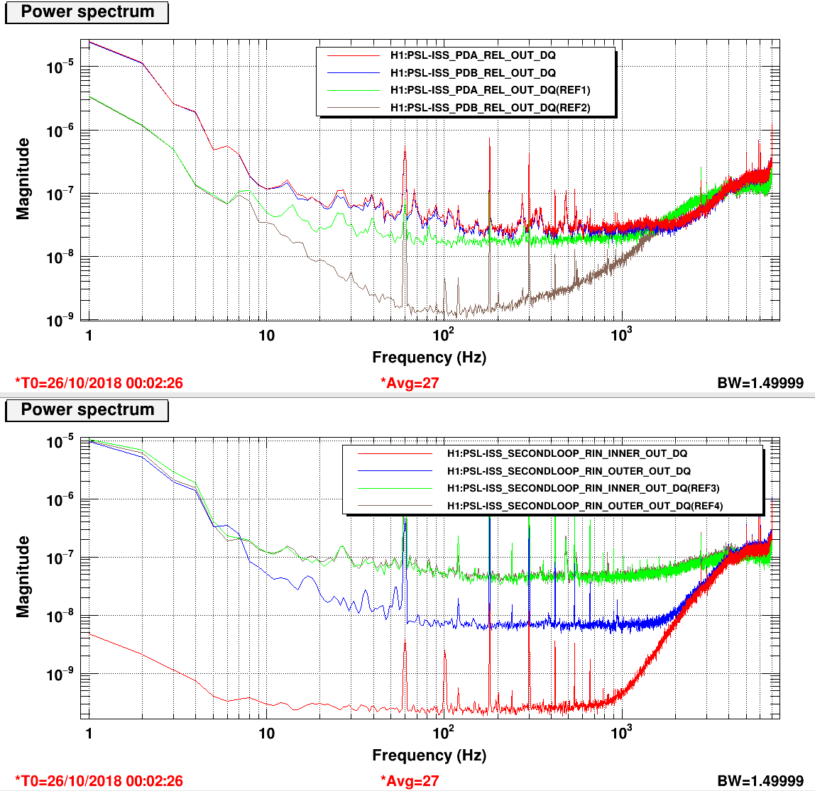
Below the RIN with 25W, ISS second loop closed, DC-coupled and boosted.
Details
The plot below shows the open loop transfer function of the ISS second loop, at 2 W, with a second loop gain of 20 W. The traces correspond to various gains of the first loop. The gain was originally set to 8 dB, giving a large gain peaking at 88 kHz. The gain is now set to 4 dB, which gives a reasonably smooth transfer function.
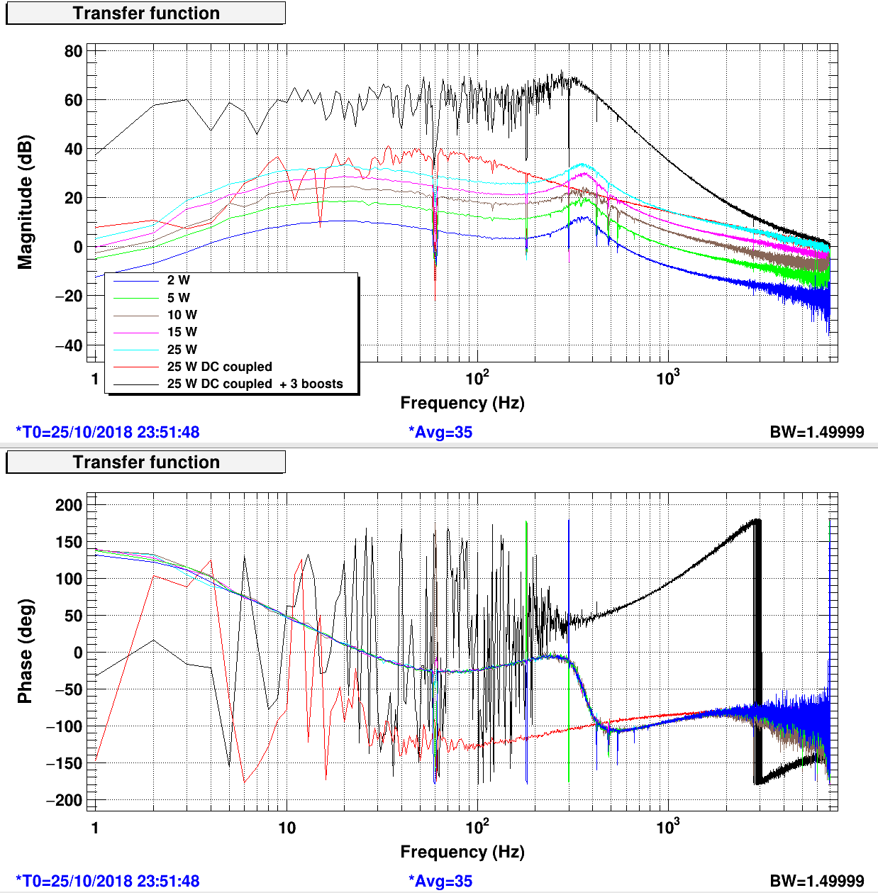
Once this issue was fixed, I could engage the ISS second loop and power up to 25 W. I measured the open loop gain of the second loop while powering up. At 25 W I D-coupled the ISS and switched on all three boosts. Open loop gains are shown below.
Some additional final remarks of other things I did today
SLOW SERVO
With the output switch open, the slow reference servo will maintain the board output near zero.
I offloaded the output of the slow offset servo H1:PSL-ISS_SECONDLOOP_REFERENCE_SERVO_OUT16 to the "bottom" offset H1:PSL-ISS_THIRDLOOP_OUTPUT_OFFSET so that the slow offset servo is around zero.
When the second loop will be engaged, the slow offset servo will switch to keeping the diffracted power near the desired value. Therefore the offset H1:PSL-ISS_SECONDLOOP_REFERENCE_DFR_CAL_OFFSET must be set to minus the diffracted power.
AC COUPLING AND PREDICTOR
In this condition, the AC coupling is off, but the "predictor" will update the AC decoupling output following the ISS second loop power, rescaled to the first ISS loop power. Set the gain of the "predictor" normalization H1:PSL-ISS_PD_NORM FM2 so that the output of the predictor normalization is near one (H1:PSL-ISS_PD_NORM_OUT16)
When the ISS second loop input is switched on (with output off) the AC coupling servo starts to work. The bias H1:PSL-ISS_SECONDLOOP_AC_COUPLING_INT_BIAS was adjusted so that the AC output when the AC coupling is off (coming from the predictor) is equal to the average value of the AC output when the AC coupling is on (meaning that H1:PSL-ISS_SECONDLOOP_AC_COUPLING_OUTPUT does not change, in mean value, when toggling the ISS input on and off).
In this configuration, with the ISS second loop input and output open, the input error signals is near zero H1:PSL-ISS_SECONDLOOP_ERR1_MON, and the output is also near zero H1:PSL-ISS_SECONDLOOP_OUTPUT_MON.
I don't understand the use of the AC coupling input offset H1:PSL-ISS_SECONDLOOP_AC_COUPLING_OFFSET
Notes
H1:PSL-ISS_SECONDLOOP_AC_COUPLING_INT_BIAS and H1:PSL-ISS_PD_NORM_OUT16 ensures that the predictor works to keep the input error signal near zero, by compensating the sum of the ISS diode signals, when the second loop is open.
even in this condition, there is an input offset in the ISS second board, so if you don't compensate for it, with the output open the board will rail. H1:PSL-ISS_THIRDLOOP_OUTPUT_OFFSET plus H1:PSL-ISS_SECONDLOOP_REFERENCE_SERVO_OUT16 is used in this configuration to keep the board output near zero when the input is near zero. Of course H1:PSL-ISS_SECONDLOOP_ERR2_MON is not zero, since that's afer the addition of the compensation offset.