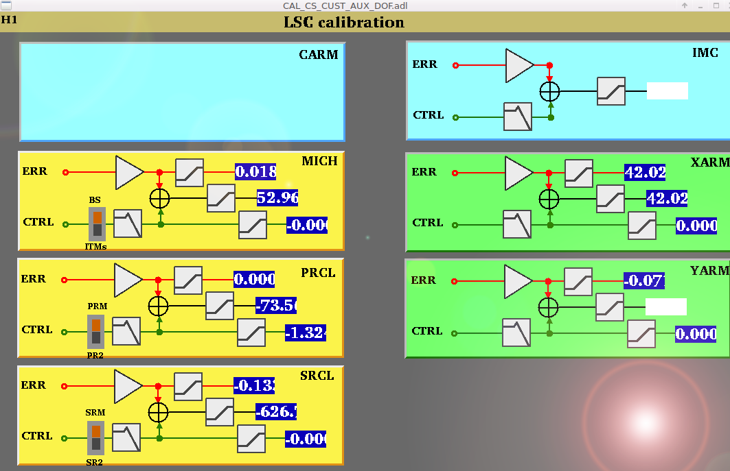
We've been noticing that the PRCL noise on the calibrated DRMI plot seems off at high frequency. I confirmed today that the cal filters in the OAF CAL DOF screen are all reasonable (ERR filters are flat, CTRL filters have HSTS M3 TF). The ERR filter gain was 3x too low: the CTRL/ERR xover was at 145 Hz instead of the actual UGF of 45 Hz, so I have added a factor of 3 to the filter.
The high frequency slope-up in PRCL is the contribution of frequency noise (above 1 kHz). Its also clear from this plot that the PRCL noise is now much higher than O1 in the 10-100 Hz band.
There is some high coherence with the SRCL length control as well as the PRC1_P WFS signals. These are not so surprising.
There is something that looks like a bandstop filter in PRC at 10-13 Hz; maybe this is a clue.
PRC length loop:
Re-measured the PRC loop shape today. In the LSC-PRC1 filter bank, I replaced the "velocity" filter with a SUS model TF so that we can estimate the loop shape w/ FOTON only (you can export the ascii TF from FOTON and import into DTT as a TF). In the attached Bode plot you can see the comparison; it is pretty good except for the phase. That is to be expected because we don't have all of the Anti-Aliasing filters included.
In the low noise state, the gain was ~3 dB too high, so I edited the ISC_LOCK script to reduce the gain to +11 in this step so the UGF = 45 Hz.
Audio:
The attached MP3 file was generated with ldv-web (https://ldvw.ligo.caltech.edu/ldvw/view). It allows us to easily get specgrams + filtered audio. For PRCL, I took the calibrated channel, bandpassed from 15-80 Hz, and then sped it up by 10x so its easy to hear with laptop speakers. The noise is breathing and popping, but I don't know what it is yet. There is a growl around 200 Hz which I think is really the 20 Hz gain peaking of MICH...


Tonight, some of the lock losses were preceeded by some 20 Hz ringing in the DRMI loops, apparent in the ringing in the excellent RLP2 LSC-BLRMS channel.
Seems like the MICH gain is slowly trending up during the locks such that it gets closer to instability and then finally saturates on of the HSTS (according to the talking box at the Operator station).
For now, I have added a line in LOWNOISE-LENGTH to reduce the gain from 2.8 to 1.7. The loop design just seems unsteady: there is a bounce mode bandstop at 17 Hz, a elliptic low pass at 35 Hz in the BS M3 stage, and a too-fancy low pass (LP80) that is making the gain sort of flat at 20 Hz.
Of course, there are many comments in the ISC_LOCK script about small gain steps. I wonder why the DRMI gains are increasing for the first 30 minutes after power up.