Summary
Today I concentrated on resurrecting the DBB. The short version is it's still not quite working right. Despite what appears to be much better mode matching than previous, the DBB PMC still refuses to lock. I think more work needs to be done regarding tweaking the mode matching solution, but I ran out of time to complete this during today's maintenance window; this work will continue next week. In addition to the DBB work, I also realigned the bullseye PD.
Details
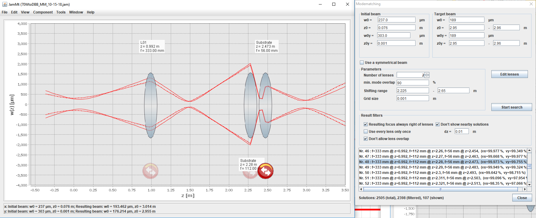
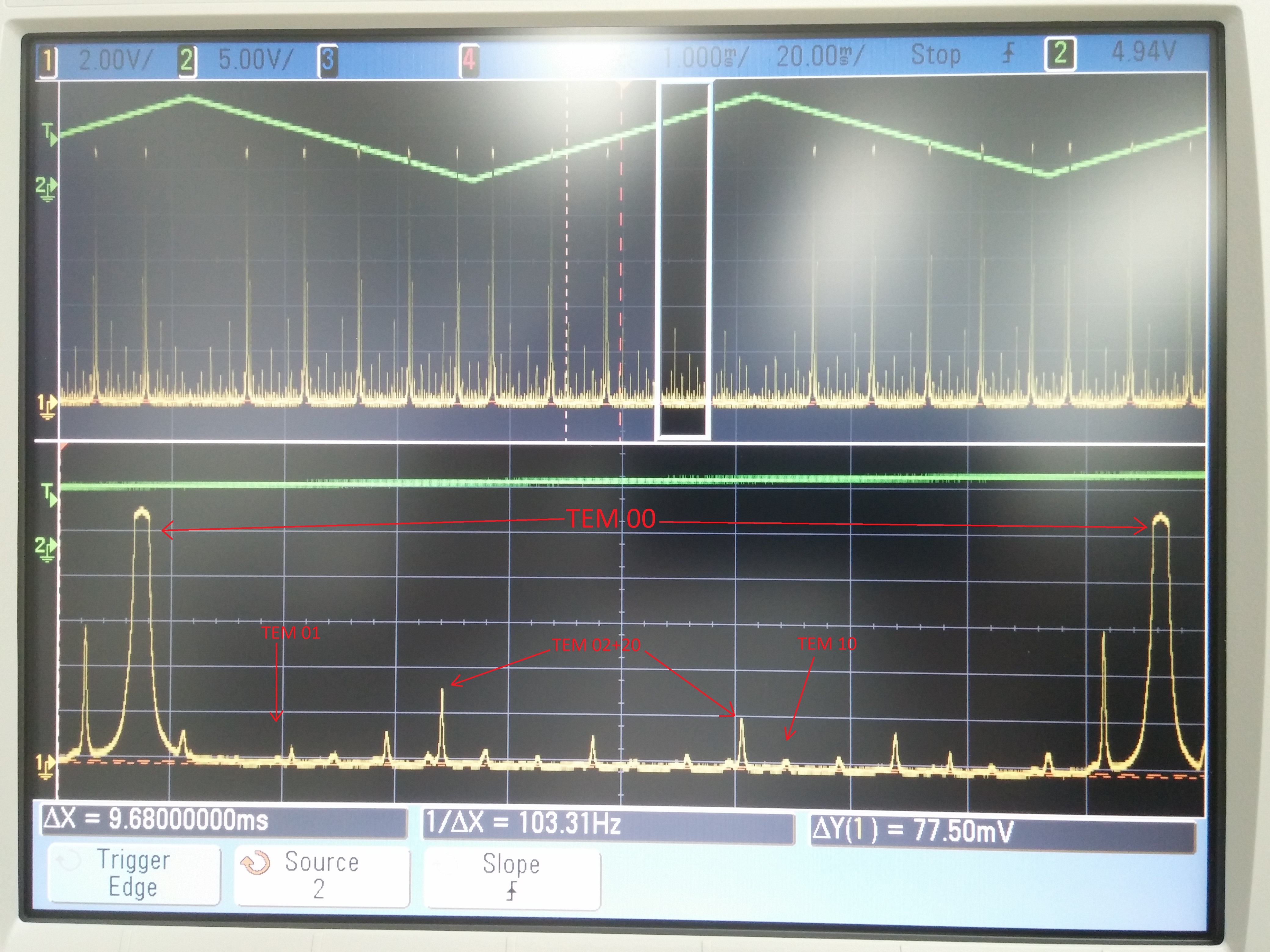
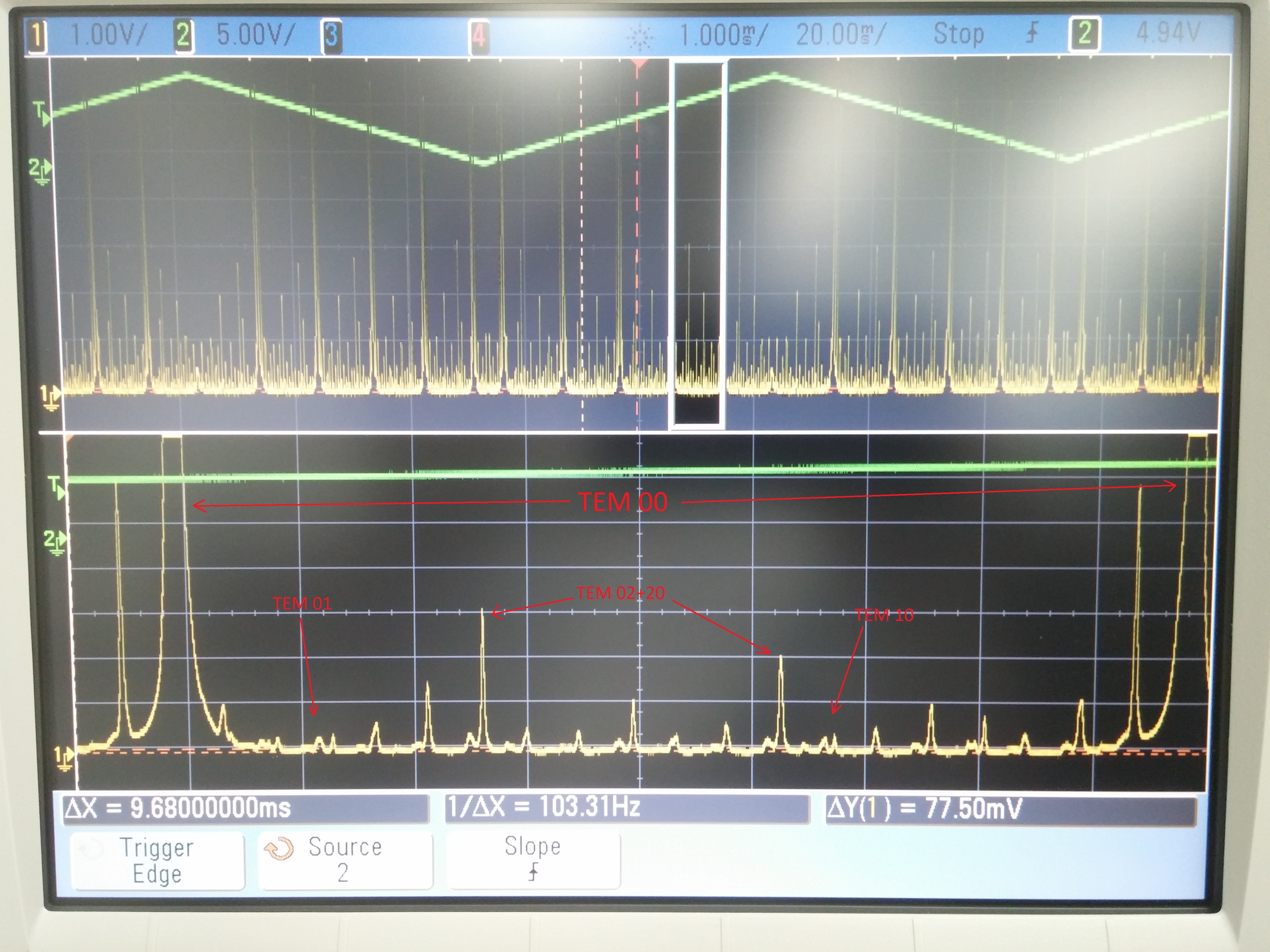
I began by implementing the mode matching (MM) solution shown in the first attachment (the solution is highlighted in the mode matching tool on the right side of the picture, Nr. 48). The lenses used have focal lengths of f1=100mm and f2=50mm (which becomes 112mm and 56mm, respectively, for a wavelength of 1064nm). I then tweaked the DBB PMC beam alignment and the positions of the MM lenses to minimize the associated peaks in a FSR scan (2nd and 3rd attachments, explanation below).
The second attachment shows a scan of a single FSR for the DBB PMC. This was taken by scanning the DBB PMC PZT at 10Hz and feeding the 40dB output of the DBB PMC's transmitted PD into an oscilloscope; the scope was triggered off of the PZT's ramp signal. The third attachment is the same scan, just zoomed in (I changed the V/div from 2.0V to 1.0V on the scope). I have also labeled the peaks we generally worry about when aligning and mode matching the DBB. The TEM10 and TEM01 peaks are minimized via alignment (as is standard for an optical cavity), while the TEM20+02 peaks are minimized via MM. As can be seen, the alignment peaks are almost gone (but not entirely, as I was focused on tweaking the MM solution; eliminating the alignment peaks is the last thing to do for the DBB and can be time consuming), but there are a number of extra peaks that I don't recognize from the last time I did this for the HPO (early 2016). These other peaks are higher-order modes that are resonant in the DBB PMC (and could be what is keeping the DBB PMC from locking). I was able to minimize a number of these peaks (there were many more when I started vs. when I finished) by tweaking the MM lens positions, so I think there is more work to do there. What is worrying to me though is the large peak directly to the left of the TEM00 peak. I don't know what this peak is, and I could not get it smaller. This peak was not present when I began tweaking the MM lens positions, it showed up as I was performing the position tweaks; in other words, while I was minimizing the MM peaks (and eliminating many of the other extra peaks along the way) this one just kept growing. This will hopefully be addressed as I finalize the MM solution next week, .
As a last test, I hooked up an old CRT monitor to the DBB PMC's CCD camera and scanned the cavity with a scanning frequency of 0.01 Hz to view the output modes (very slow so the output modes can be seen, any faster and they fly by too fast for visual identification); I see many radial modes that look to me like higher order Laguerre-Gaussian modes, indicating that there is more MM work to do. I am encouraged by the fact that this MM solution seems to be viable with some tweaking. The last one we attempted didn't work, at all (the resulting focus was ~8 inches short of where it was supposed to be...). To be continued next week.
In addition to the DBB work, I also realigned the bullseye PD. I noticed last week that there appeared to be no light on this PD (my apologies, I informed Jenne and Shiela of this but completely forgot to alog it). The beam path for the bullseye PD had been co-opted at some point for taking 70W amp beam propagation measurements, and had not been restored. In light of this, I restored this beam path and aligned the beam onto the bullseye PD; it is now ready for use. In the future (and this applies to myself as well), should this beam path be needed for any temporary purpose (such as taking a beam propagation measurement for the 70W amplifier) we need to be sure to restore it so the bullseye PD can actually be a useful diagnostic tool.