craig.cahillane@LIGO.ORG - posted 04:09, Thursday 08 November 2018 (44999)
What is going on with frequency noise?
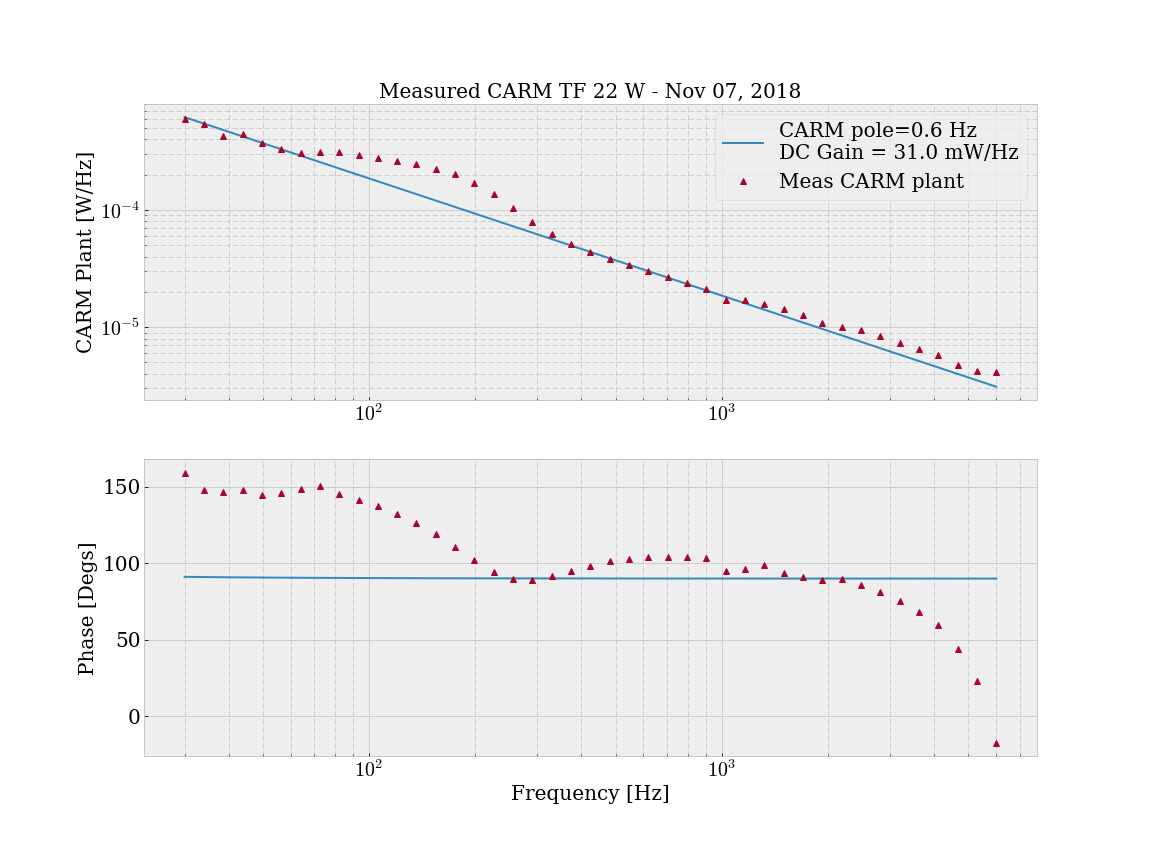
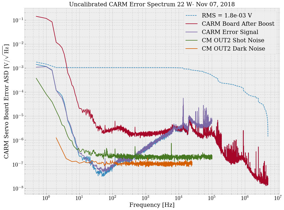
The measured CARM error spectrum seems like it could be explained by IMC sensing noise. I am more confident of the calibration of the spectrum, thanks to Rana's input. The story so far At 22 W NOMINAL_LOW_NOISE, if I measure the Common Mode Board (CMB) OUT2 error point, I get a slope that rises like ƒ. If I assume the dominant noise everywhere at the CARM error point is physical changes in the laser frequency incident on the IFO, then to calibrate the error signal to in-loop frequency noise, I divide by the CARM plant, which is a 0.6 Hz pole. This makes our calibrated frequency noise spectrum rise like ƒ2. This seems to disagree with past measurements by Evan (plot 2), which featured incident frequency noise rising like ƒ. CARM Calibration ith 22 W and PRG ~ 47, assuming a CARM pole of 0.6 Hz, we get a CARM DC optical gain of 31 mW/Hz. (Plot 3) I'll briefly explain the cal method.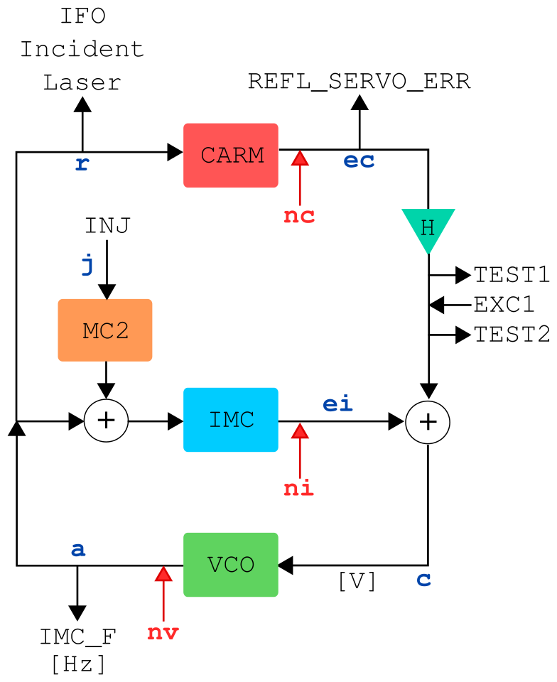
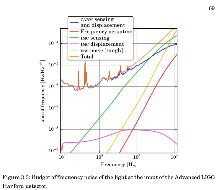
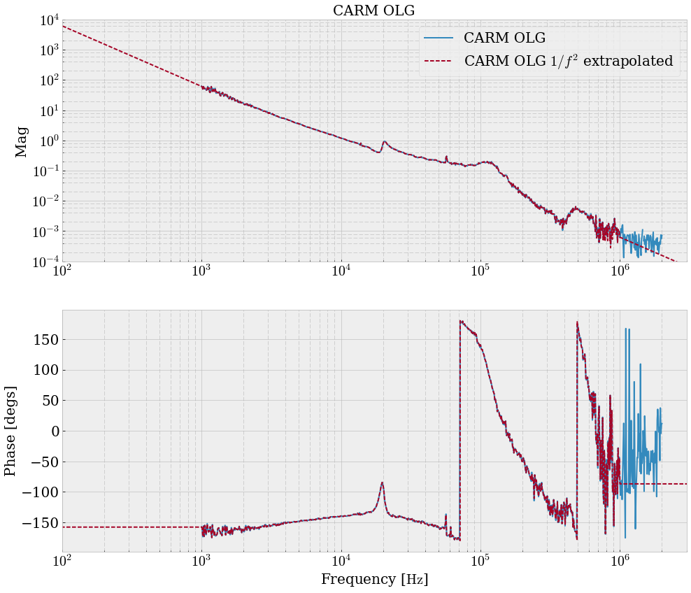
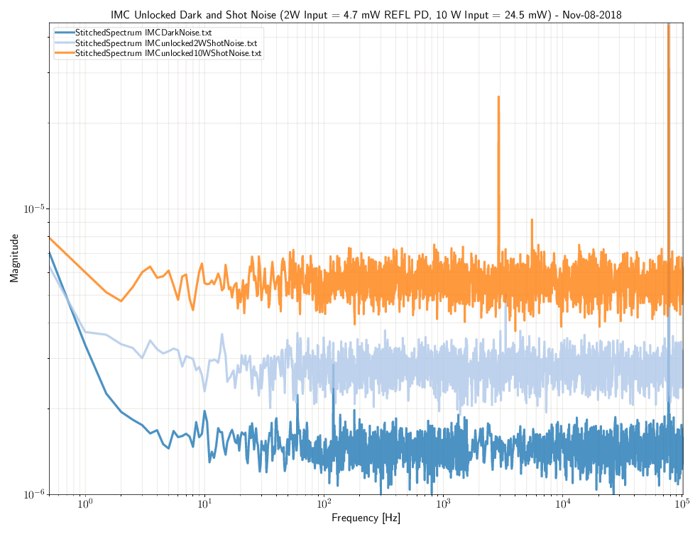
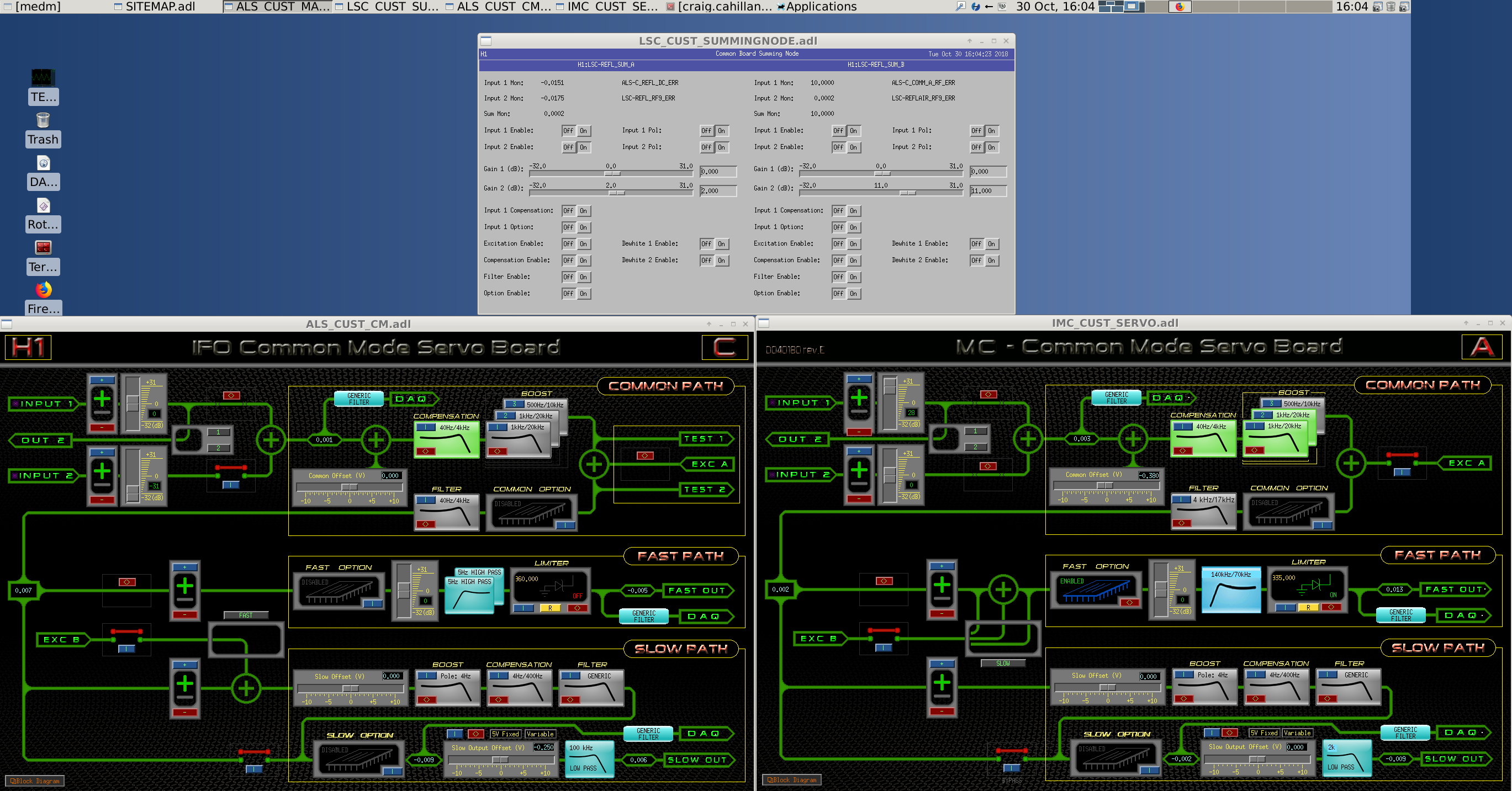
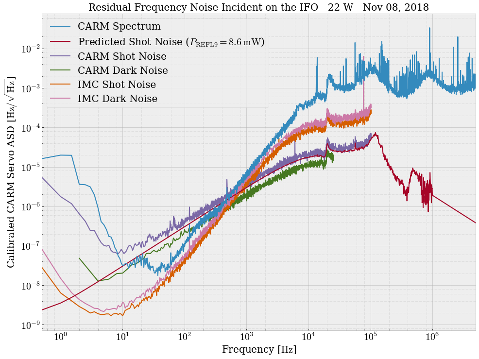
IMC_Fis actually the control signal sent to the VCO calibrated into Hz,REFL_SERVO_ERRis the CARM error signal in volts, andINJis our length injection into the IMC MC2 suspension in counts. First we get a CARM OLG:CARM_OLG = TEST1/TEST2 = CARM * H * VCO / (1 - IMC * VCO)I note here that the CARM closed loop gain has the convenient expressionCARM_CLG = CARM_OLG/(1 - CARM_OLG) = CARM * H * VCO/[1 - VCO * (IMC - CARM * H)]and that at frequencies less than the CARM UGF of 10 kHz,CARM_OLG ≈ - CARM * H / IMCThen we calibrateINJinto Hz by locking the IMC only and measuringIMC_F/INJ. At frequencies below the IMC UGF of 75 kHz, we haveIMC_F/INJ = MC2 * OLG_IMC/(1 - OLG_IMC) ≈ MC2.We get a fit ofMC2(f) = 10.3/ƒ2 [Hz/cts]. Then we lock CARM and measureINJtoREFL_SERVO_ERR. This TF looks likeREFL_SERVO_ERR/INJ = MC2 * IMC * VCO * CARM/[1 - VCO * (IMC + CARM * H)] = CARM_CLG * MC2 * IMC / H ≈ MC2 * IMC / H.Now, we combine our measurements to get theCARMplant TF (Plot 3):CARM ≈ - CARM_OLG * (REFL_SERVO_ERR/INJ) / (IMC_F/INJ)To get the CARM OLG down to 100 Hz, I extrapolated it's 1/ƒ2 behavior (Plot 6), not perfect but good enough for now. The "measured CARM" Plot 3 gives a pretty trustworthy 1/ƒ spectrum, considering it was the combo of three measurements. Noisebudget The CARM noisebudget is shown in Plot 9. Using the loop above,nvis laser noise,niis IMC sensing noise, andncis CARM sensing noise. For residual frequency noise I getr = CARM_CLG * [nv / (CARM * H * VCO) + ni / (CARM * H) + nc / CARM]I measured the CARM shot and dark noise last week, and yesterday got the IMC shot and dark noise. The IMC shot noise measurement was taken with 4.7 mW on the IMC REFL PD, but while we're locked at 22 W there's 0.7 mW on there. According to Plot 7, it seems that in lock we could be dark noise limited on the IMC. I'm using a transimpedance of 2900 V/W for REFL9, 2 dB on for sum node gain, and gain sliders/boosts according to Picture 8. To test this noisebudget, we can increase the CARM boosts (H) slightly and see if our spectrum flattens out as CARM wrests more actuation authority from the IMC. Since we are concerned with frequency noise levels around 4.1 kHz now, we ought to try pushing up the IMC and CARM gains. Extras Current PD Power (alog 44947)NOMINAL_LOW_NOISE Full Lock --------------------------- Input Power = 22 W REFL power = 9 mW IMC REFL power = 1.8 mW (used to be 0.7 mW at the time of the CARM spectra measurements, IMC REFL power is higher now)The Past REFL9 Transimpedance Hall-Yu September 2015 Frequency Noise Dwyer-Hall-Driggers October 2016 Frequency Noise Ballmer-Hall Freq to DARM Coupling Sigg Freq Noise
Images attached to this report