Terry, Daniel, Haocun, Nutsinee
After running into several problems of EOMs not working as they should, we finally installed a New Focus 4002 EOM in the green path with half wave plate at the input and output rotated 45 deg. The whole set up is to use EOM as an amplitude modulator so we can inject intensity noise into the OPO loop. We have always had a lot of unexplained noise and we're hoping intensity fluctuation+crystal interaction could explain at least some of them.
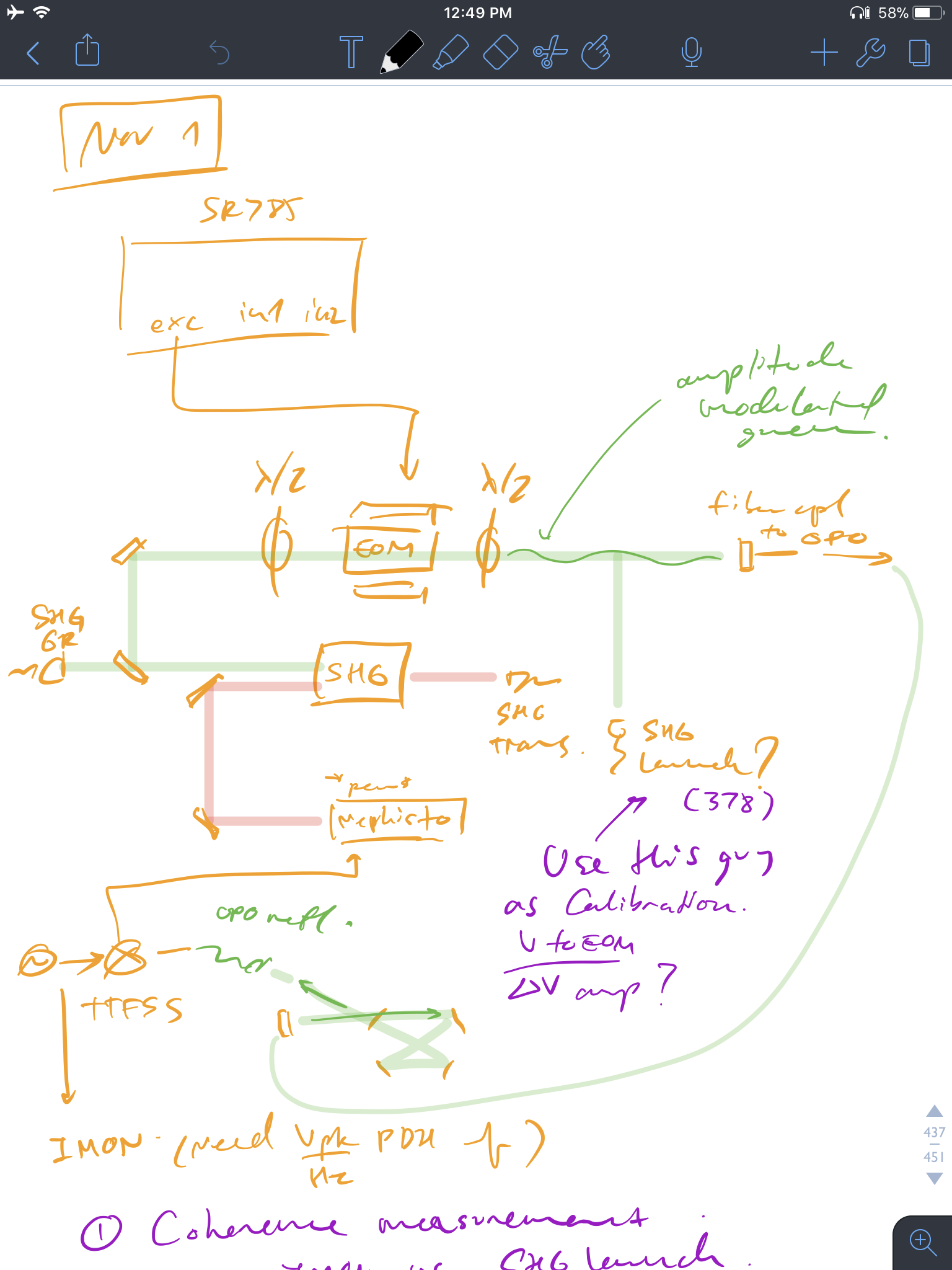
We hooked up SR785 swept sine excitation to the EOM while OPO is locked. Got about 7% of intensity modulation. TTFSS I-MON goes to CH2 and SHG launch diode readout (monitors what goes to the fiber coupler) goes to CH1.
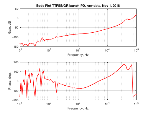
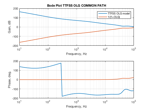
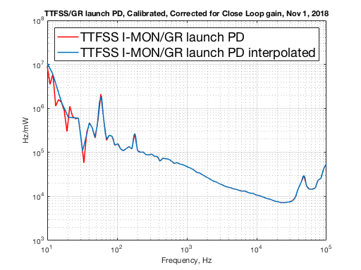
This data is then multiplied by OPO open loop gain and calibrated into Hz/mW
(V_ttfss/V_GRPD) * (FWHM Hz/ I-MON PDH Vpk) * (GRPD Transimpedance V/A) * (GRPD Responsivity A/W)
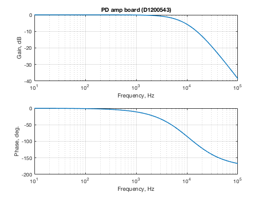
PD gain and dual DC photodiode amplifier board transfer function are included.
The diode response "pole" is around 8kHz, which is the turn around point of the plot above.
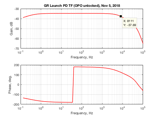
(A fun fact, the response of the EOM to swept sine signal drops as you go towards DC)
If we were to repeat this transfer function with OPO locked, we got a tail biting effect going on as well.
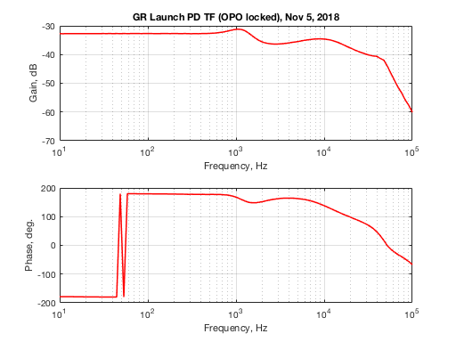
Note that the phase here could change depending how much power is going to the temporary EOM we installed. When the rejected (wrong polarization) diode reads about the same as the launch diode the phase above can flip 180 deg. This is likely due to EOM crystal changing the output beam polarization depending how it's heated. With this unreliable response we concluded that the A/EOM set up is no good for power fluctuation control.
Moving on.
Now that we have Hz/mW calibration, we can use the launch diode to figure out how much phase noise do we expect LO to see (calibrated into mW then multiply by Hz/mW).
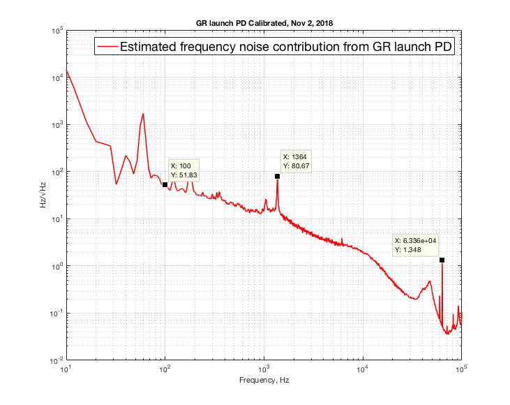
Note that at 100Hz the frequency noise is almost as bad as Mephisto free running (100Hz/sqrt(Hz) at 100Hz). I pointed out the 1.3kHz line because it also shows up in OPO spectrum, and it is what killed our lock when HAM6 was in air (the peak was much worse in air). This line is to be investigated. 60kHz line may or may not matter. Could it be a laser PZT resonance (?). I will be posting more noise budget (OPO, LO) in a separate log.
Now convert the plot above into radian and calculate the rms.
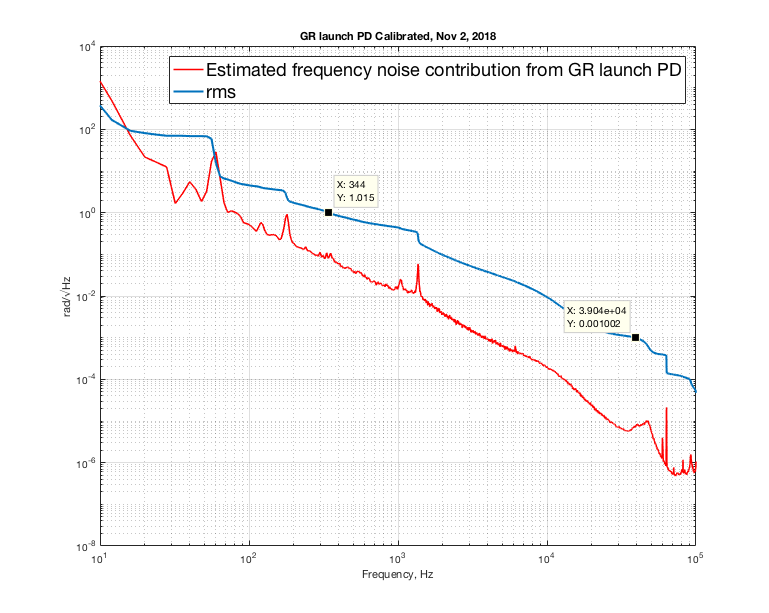
It's 1 rad /sqrt(Hz) at 344Hz and doesn't go down to a mrad until 39kHz. The LO loop have to have suppression of 40dB at 100Hz and a UGF of at least at 39kHz to keep sqz phase noise down to mrad level (note that this is all green projection so there's a factor of 2 down, but that still doesn't help). This is why using a PFD and slow path signal to OPO PZT alone didn't work. Currently we feed the fast path signal to TTFSS additive offset which gives LO loop a UGF of ~50kHz.