We prepared filters for digitally compensating the Sidles-Sigg torque to achieve power-independent ASC plant. Currently we only consider DHARD YAW whose measurement seemed to match to the plant (LHO:43763; up to the potentially non-minimum delay at 1.8 Hz, see, e.g., LHO:43822).
The filters are now put in the DC5_Y filter bank, and the subtraction can be realized by routing the DHARD error signal (AS_A_RF45_Q) to DC5 and connecting the output to DHARD Y.
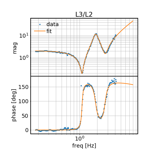
In the filter banks, FM1 is simply a high pass (zero at 0 Hz, pole at 0.1 Hz) to compensating for the offloading to M0. FM2 is the (L3 torque to angle) / (L2 torque to angle) transfer function based on measurements. See the first attached plot. The FM3 is the negative of the Sidles-Sigg torque coupling coefficient = (2*P_arm/c * dy/dth) in [Nm/rad]. Here dy/dth is the angle-to-spot-position conversion factor and for aLIGO Hard mode it is -4.5e4 [m/rad]. We normalize the P_arm to 50 kW. Lastly, FM4 calibrates the torque into appropriate ct going to L2 (numerical value is 1.6e+9) and FM5 calibrates the ct into the filter bank back to DHARD misalignment in rad with a numerical value of [4.5e-12].
To engage the compensation filter we should put a dc gain of (- arm power / 50 kW).
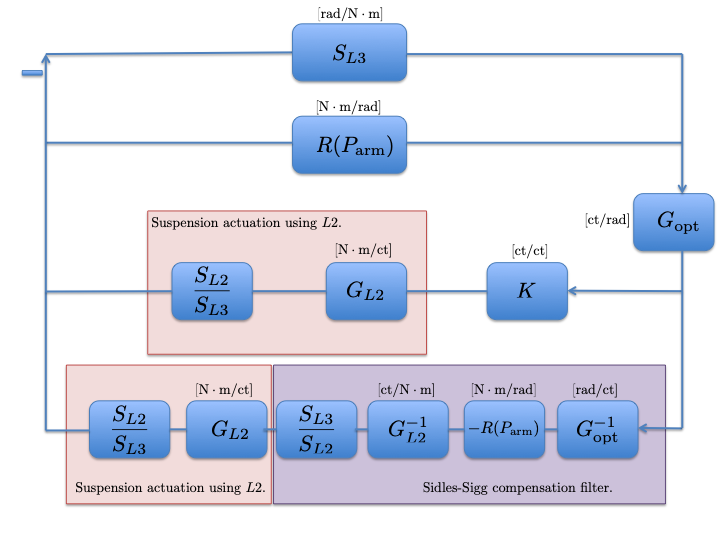
This is to mirror LLO:41836 to provide a more detailed illustration on how the Sidles-Sigg radiation pressure compensation scheme can be implemented.
Here we define:
* S_L2 (L3) is the *FREE PENDULUM* torque to angle transfer function from the L2 (L3) drive to L3 angular displacement.
* R(P_arm) is the radiation torque feed back from angle to torque (AC angular fluctuation changes the AC spot position on the test mass, which then couples with the DC arm power to create an AC torque).
R(P_arm) = - 2 (P_arm / c) * dy/dtheta, where dy/dth = -4.55e+4 [m/rad] for the hard mode, and dy/dth = 2.1e3 [m/rad] for the soft mode.
* G_opt is the WFS optical response from physical angle to counts going into the suspension actuator. It is around 2-3e+10 [ct/rad] for the hard mode.
* G_L2 is the gain from count input to torque exerting onto L2 stage and its numerical value is 6.3e-10 [Nm/ct]. Together with S_L2 it forms the suspension actuator. (For simplicity of modeling the Sidles-Sigg torque we put the L3 stage suspension into the top line as it is the test mass that interacts with the optical torque. For the ASC control, on the other hand, we use L2 stage, and thus we need to put S_L2/S_L3 to cancel the L3 response shown in the first line).
* K is the regular ASC control filter.
* What is shown in the purple box is the content going into the Sidles-Sigg compensation filter.
What is *NOT* shown in the diagram:
* In the actuator (pink box) there is also signal offloading to M0 (for LHO) / L1(for LLO), which is a simple integrator and the crossing frequency with the L2 stage actuator is tuned to 0.1 Hz.
* To compensate for this offloading, we need an extra high-pass (zero at 0, pole at 0.1 Hz) in the Sidles-Sigg compensation filters. This is not shown in the diagram but put in the real filter.