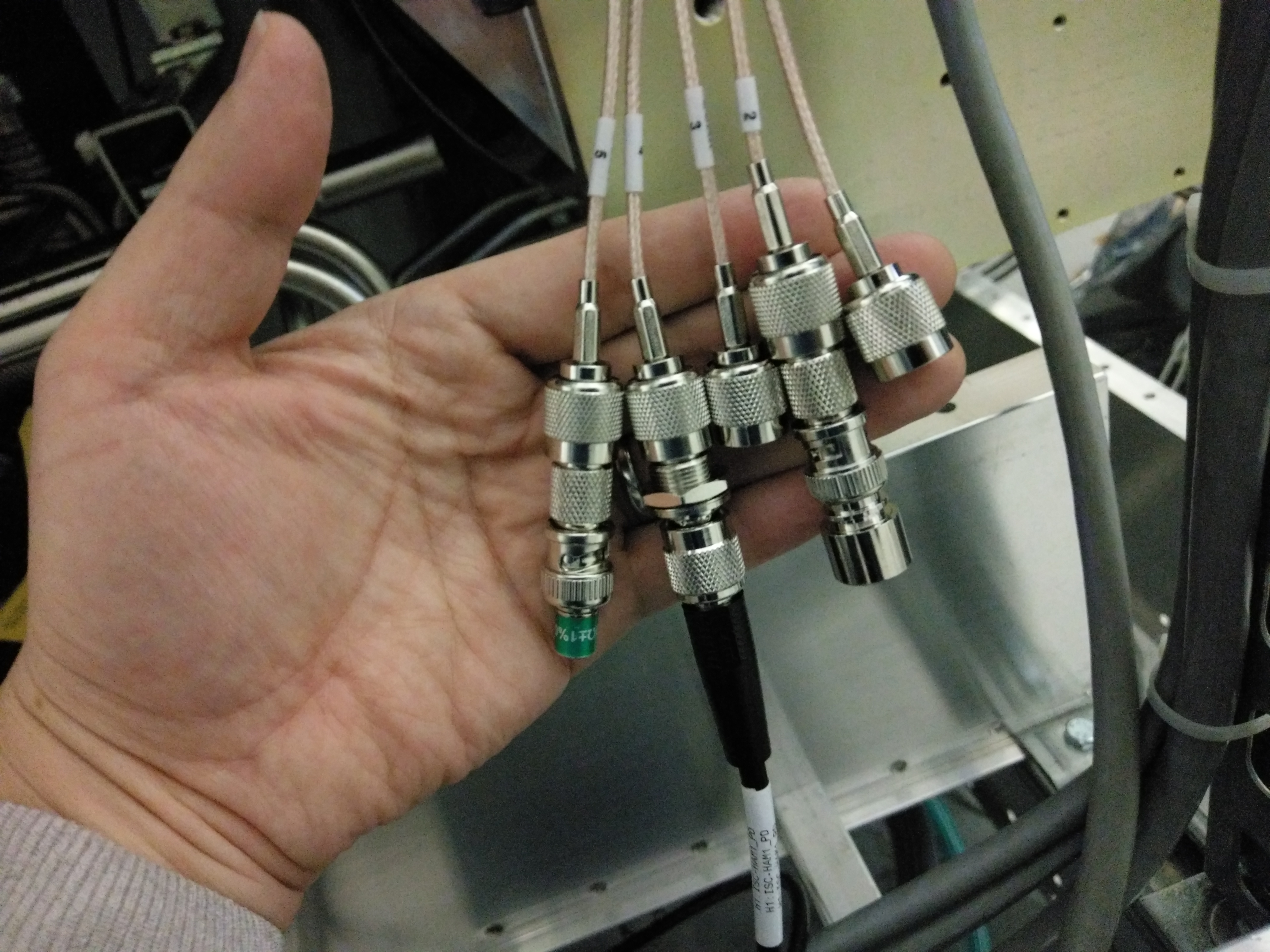
We connected the 5-way coax to TNC adapter that Fil has made to the chamber. 5-way coax cable assignment is in D1300466.
| cable 1 | cable 2 | cable 3 | cable 4 | cable 5 |
| Single ended DC | Test in | Test out | RF LOW (9MHz) | RF HI (45MHz) |
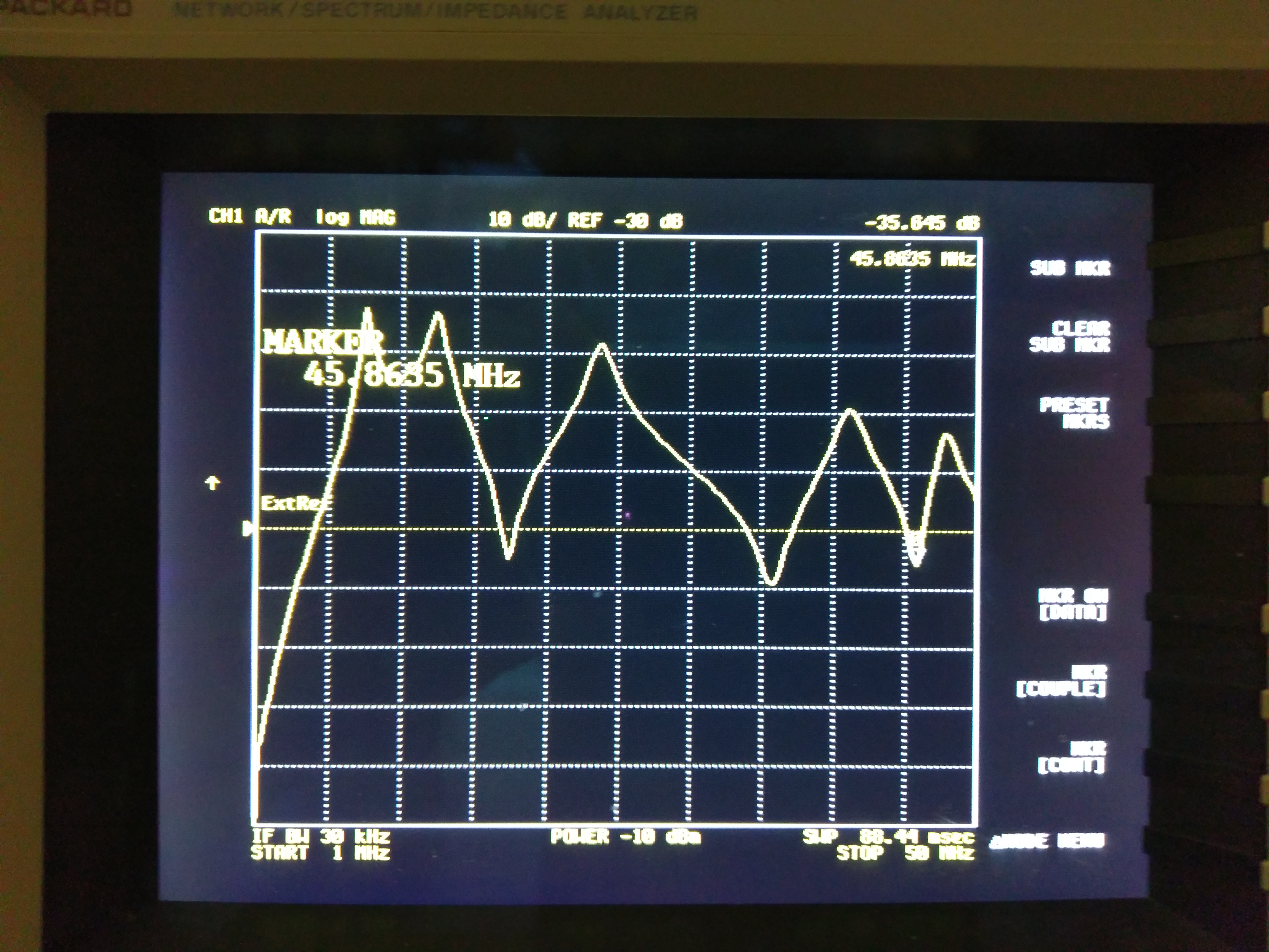
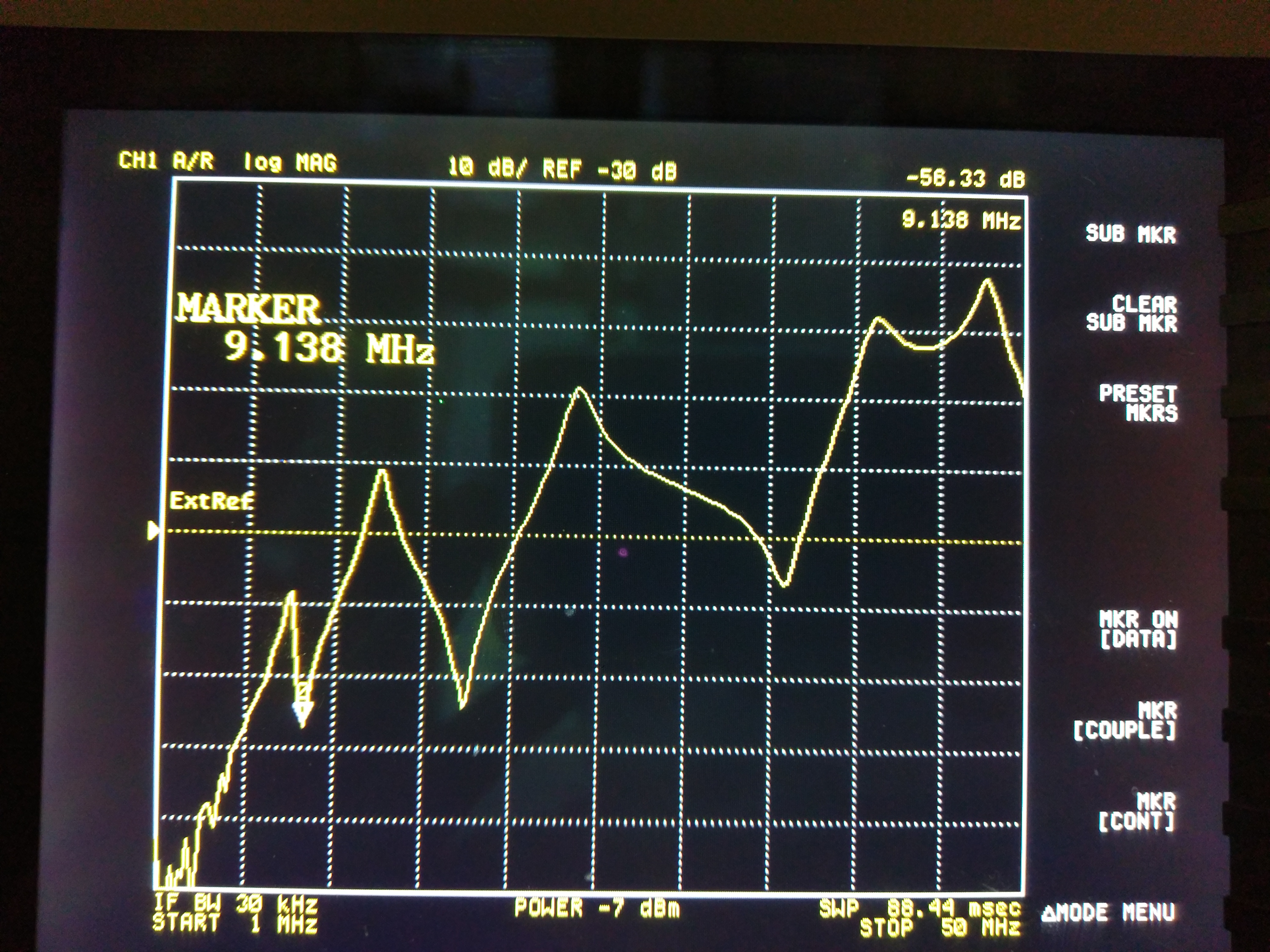
We measured the TF from cable 2 to cable 4 while cable 5 was terminated (attachment 1), then from cable 2 to cable 4 while cable 4 was terminated (attachment 2) and both made sense.
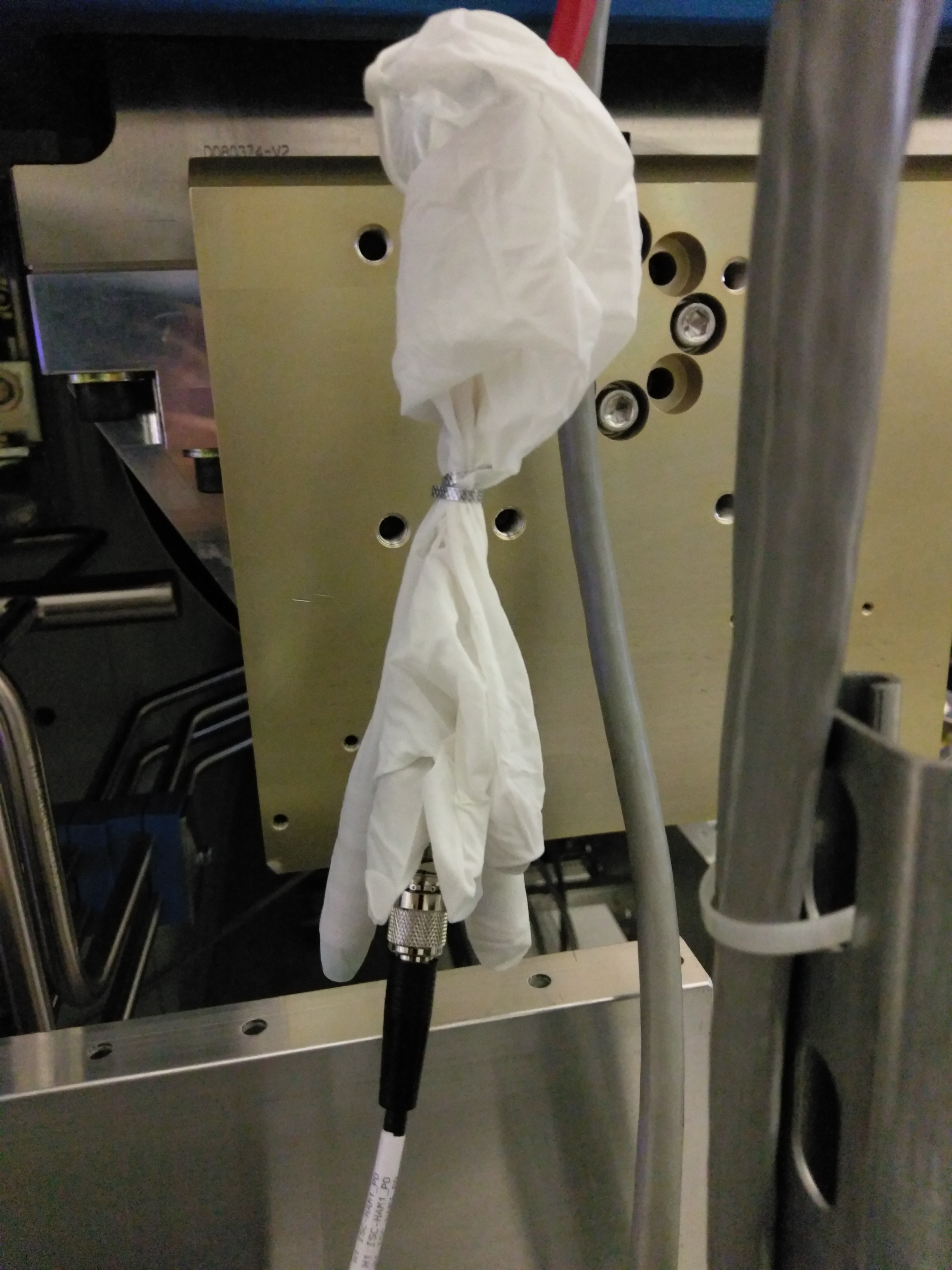
The problem of this configuration is that shells of TNCs are touching with each other (attachment 3, note that cable 2 and cable 5 are terminated). We put cable 1, 2, 3 and 5 inside different fingers in a glove to insulate things from each other (attachment 4).
For the moment 9MHz connector is exposed but it's not touching any surrounding metals.
For a short while we locked MC with 200mW and measured the coherence between REFL_A and REFL_B 9MHz, and it also made sense (see Georgia's comments).
After ground loop checks we will isolate these with heat shrink.
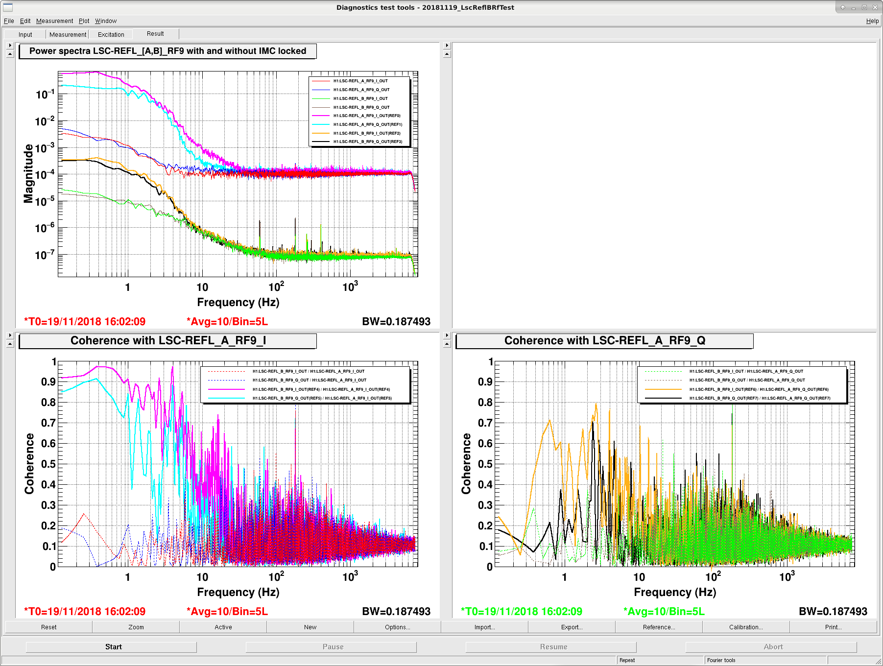
I'm attaching the power spectra of, and coherences between, LSC-REFL_A_RF9_I, LSC-REFL_A_RF9_Q, LSC-REFL_B_RF9_I, and LSC-REFL_B_RF9_Q, with and without light on the photodiodes.
Blue, red, green, and brown traces are with the IMC offline.
In the top plot cyan and pink are REFL_A_RF9 with the IMC locked with 200 mW, orange and black are REFL_B_RF9. Signal is seen on both photodiodes, there is a gain difference between them.
Bottom left plot shows REFL_B_RF9_I and Q coherence with REFL_A_RF9_I; bottom right plot shows REFL_B_RF9_I and Q coherence with REFL_A_RF9_Q. Higher coherence is seen with REFL_A_RF9_I, not surprising since REFL_B has not been phased.