Introduction
The goal of this entry is to describe a method to characterize the non stationary of SRCL noise coupling to DARM, by identifying the coupling modulation. In the near future this should also provide a technique to do non-stationary noise subtraction.
Observations
When SRCL noise is injected and the SRCL feed-forward path is active, we see
- DARM noise can be made to increase by a factor ~100 at all frequencies above 10 Hz
- but the coherence between DARM and SRCL is very good only below 20 Hz. Above it averages to a level of 0.8-0.9, which is much lower than what you would expect given how much the SRCL noise is dominating DARM
In the plot below, the coherence is computed while SRCL noise was being injected.

The observations above seems to hint to some non-linear or non-stationary coupling of SRCL to DARM, especially at frequencies above 20-30 Hz
Algorithm
Past observations showed the SRCL coupling to be modulated by residual angular motion. To characterize this more precisely, I used the following algorithm:
- assume the source of the noise is SRCL (LSC-SRCL_OUT_DQ to be precise) and that the modulation is slow and due to residual angular motion (ASC-*_INMON to be precise)
- build a set of modulated noise signals, by multiplying SRCL with each of the angular signal independently (and by each of the ASC signal squared to include quadratic modulations). If s is the source SRCL noise, and a_i are the ASC signals, we build s_i = s a_i
- we then build a linear combination of the modulated signals
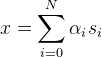
- We can look for the optimal value of the alpha_i coefficients to maximize the coherence of this signal with DARM, or equivalently to minimize the power spectral density of the subtracted signal (DARM - x)
- We can allow the coefficients alpha_i to be frequency dependent and complex, thus describing the transfer function from each modulated signal to DARM
- A closed form solution can be found, making this approach fast to implement
Although the alpha_i are frequency dependent, they are not enough to describe any frequency dependency in the way the angular signals are affecting DARM. For example, if one of the angular signals modulates the coupling with a delay, or after the signal is passed through any time-domain filter, this algorithm will not model that. In other words, this algorithm is capable of finding and modeling things like DARM = TF[ SRCL * ASC_i] but not like DARM = SRCL * TF[ASC_i].
This algorithm is essentially equivalent to implementing an a-causal Wiener filter that uses as input the modulated signals s_i
Results
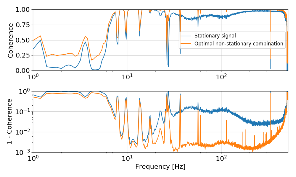
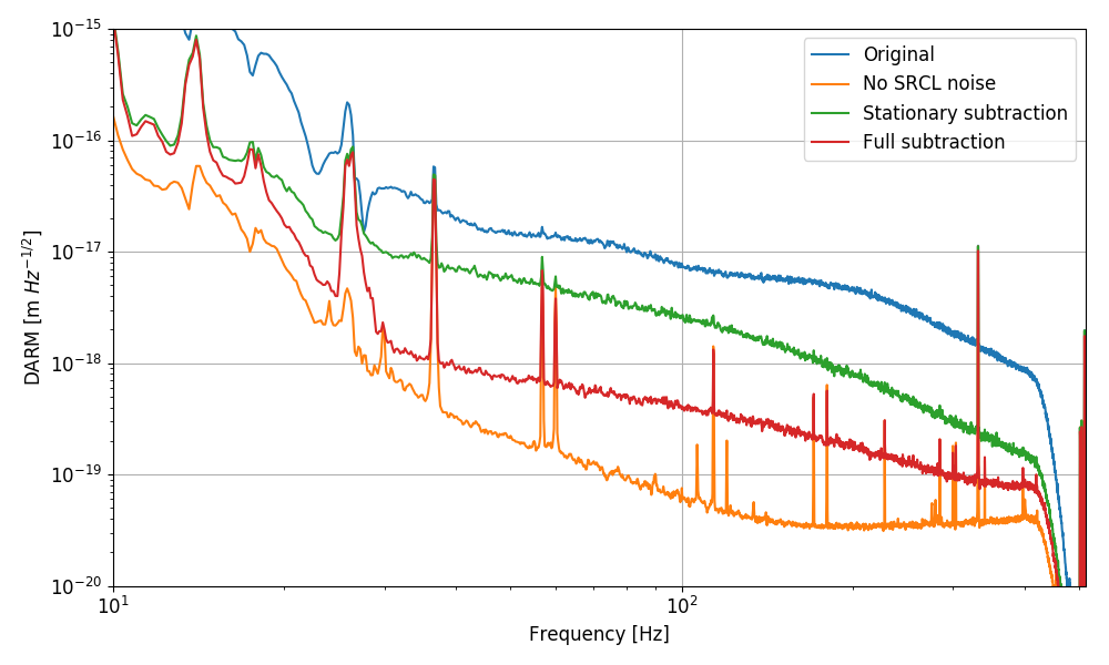
The two plots below shows the effectiveness of this algorithm. While the coherence of DARM with SRCL is relatively low during the noise injection, the coherence of the (optimally) modulated signal is high everywhere, as one would expect given the SNR of the noise injection. The second plot shows that if we subtract SRCL from DARM using a constant transfer function (i.e. DARM - TF * SRCL) we cannot get more than a factor ~10 subtraction. However, if we use the signal x that takes into account the modulation, we can get a much improved subtraction at all frequencies. For comparison the plot shows a typical level of DARM noise.
The algorithm work in frequency domain, so for each of the modulation channels (SRCL times a_i or a_i^2), we get a transfer function that determines how that couples into DARM. I don't have a way yet to rank the most important modulations, but simply looking at the amplitude of the transfer function gives an idea of which angular signals are the most important. The plot below shows the amplitude and phase of each transfer function. So the title of each panel gives you the source of the modulation (1 means no modulation) and the plot is actually the transfer function from SRCL times that modulation to DARM.

The most important modulations are: DHARD_P, DHARD_Y followed by SRC1_P, MICH_P and PRC2_P
Next steps
This algorithm does not provide yet a way to build a time domain subtracted channel. To do that we have to convert the transfer functions to time domain filters.
- one approach would be to just fit the TF obtained above, as we would do for a simple linear subtraction
- one other approach would be to do the subtraction using FFT, which might be ok for off-line subtraction, but cannot be implemented online
- the most interesting approach would be to extend te algorithm to fit directly IIR filters, instead of a frequency domain transfer function.
I will try out (1) in the near future. (2) can be left as a fallback solution, since it's known to be working.
I have some plans to try (3), which is the most interesting of the three approaches. If working, it might also provide a way to directly gte IIR filters from the Wiener algorithm.
Finally, sooner or later, I will prepare a write-up of the algorithm for the DCC.