jeffrey.kissel@LIGO.ORG - posted 15:41, Monday 26 November 2018 (45501)
H1 HAM1 Table Top (TT) L4Cs Calibration
J. Kissel, H. Radkins
Hugh and I sat down to reconcile the calibration for the four new HAM1 Table Top L4Cs, currently stored in the frames right off the ADC as
H1:HPI-HAM1_TT_L4CINF_H1_IN1_DQ
H1:HPI-HAM1_TT_L4CINF_V1_IN1_DQ
H1:HPI-HAM1_TT_L4CINF_V2_IN1_DQ
H1:HPI-HAM1_TT_L4CINF_V3_IN1_DQ
eventually, once we get the Cartesian transformation matrices up and running, we will have pre-calibrated versions of the channels stored in the frames as H1:HPI-HAM1_TT_L4C_${CARTDOF}_DQ, where CARTDOF = X, Z, RX, and RY.
The standard signal chain gain calibration for an in-vacuum L4C (from D1001575) is:
V V V V 2^16 ct ct
275 --- * 44 --- * 2 --- * 7 --- * ---- -- = 2.77544960e9 ---
(m/s) V V V 40 V (m/s)
|----------|----------|-------------------|-----------|
L4C L4C L4C Interface GS
Generator In-vac (high gain mode) 16-bit
Constant Preamp (low gain 7 > 1) ADC
>> 3.603e-9 (m/s) / ct = 3.603 (nm/s) / ct
These table-top L4Cs, however, are run through GS13 interface chassis board (D1002706), in which the gain can switch between 1 and 10, instead of the L4C interface chassis board (D1002739) which switches between 1 and 7, as described above. Thus, the calibration should be,
V V V V 2^16 ct ct
275 --- * 44 --- * 2 --- * 10 --- * ---- -- = 3.96492800e9 ---
(m/s) V V V 40 V (m/s)
|----------|----------|-------------------|-----------|
L4C L4C L4C Interface GS
Generator In-vac (high gain mode) 16-bit
Constant Preamp (low gain 7 > 1) ADC
>> 2.5221e-09 (m/s) / ct = 2.5221 (nm/s) / ct
In additon, the L4C is an inertial sensor with damped resonance at 1 +/- 0.05 Hz and a Q of ~2, so to invert its frequency response, we must include
- two poles at 0 Hz,
- a complex pair of zeros at 1 Hz with a Q of sqrt(2) (or a phase between the poles of 45 deg).
- a Q reduction, soft-notch filter filter at 1 Hz, with Q ratio of 1.81398 to 0.707107 (i.e. sqrt(2)/2 i.e critically coupled)
Thus to calibrated the input off of the ADC for these new L4Cs in DTT:
Channel: H1:HPI-HAM1_TT_L4CINF_H1_IN1_DQ (or V1, V2, or V3 instead of H1)
Units: m/s
Gain: 2.5221e-8 (m/s) / ct for low gain mode, (or 2.5221e-9 for high gain mode)
Poles: 0,0, 0.707107 0.707107
Zeros: 0.707 0.707, 0.275637 0.961262
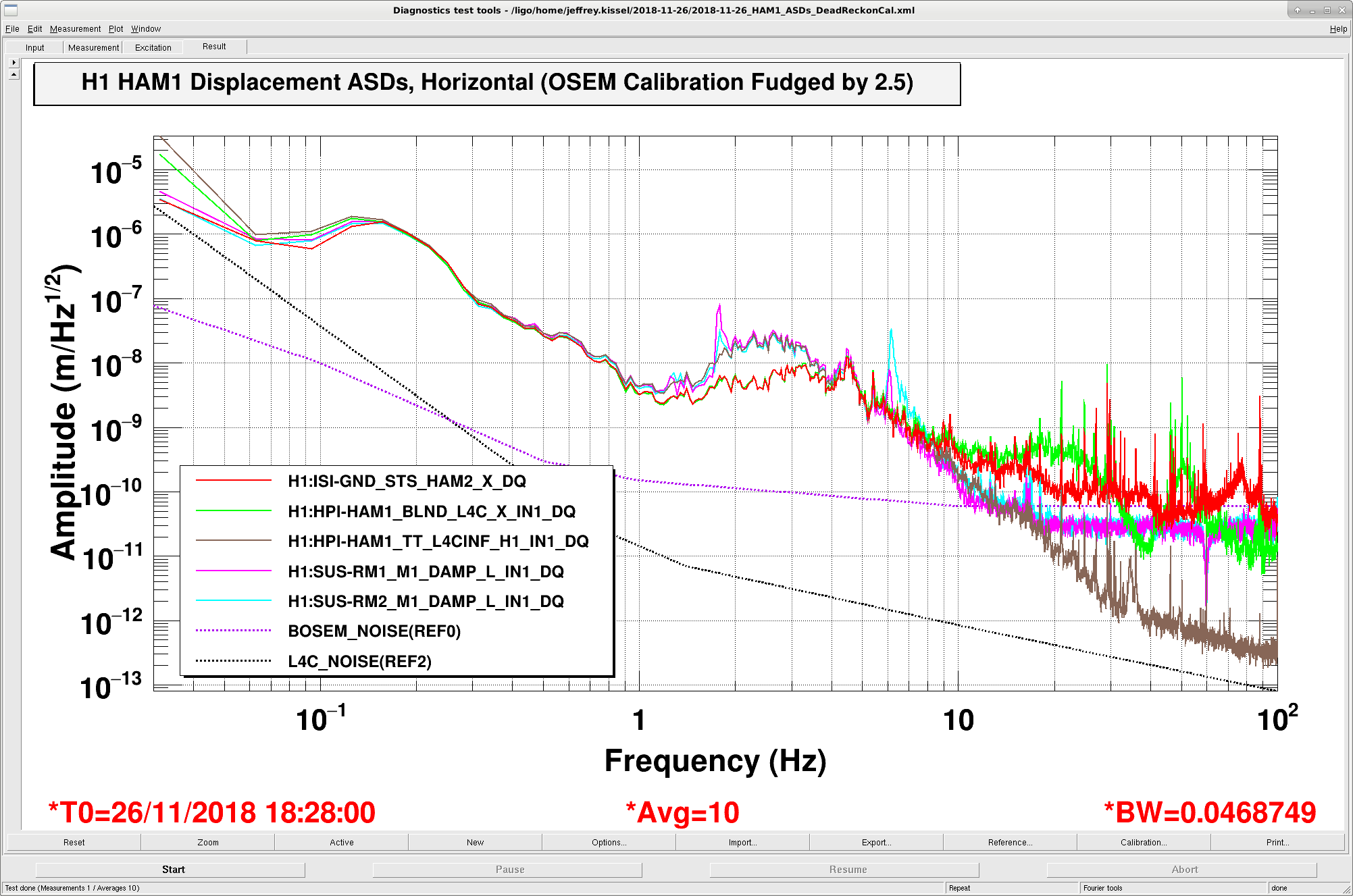
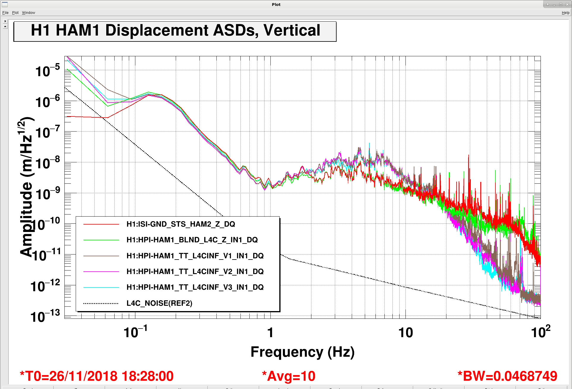
We've verified this calibration against the following sensors in and around HAM1 with HEPI offline, and the RMs undamped:
Channel: H1:ISI-GND_STS_HAM2_X_DQ (or Z) (pre-calibrated to asymptote to a gain of 1 nm/s at high frequency, with no response inversion)
Units: m/s
Gain: 1e-9 (m/s) / (nm/s)
Poles: (none) << no need to invert 0.0083 Hz STS resonance, since we're looking at f > 0.03 Hz
Zeros: (none) << no need
Channel: H1:HPI-HAM1_BLND_L4C_X_IN1_DQ (pre-calibrated into an ideal 1 Hz inertial sensor, whose gain asymptotes to 1 nm/s at high frequency)
Units: m/s
Gain: 1e-9 (m/s)
Poles: 0,0
Zeros: 0.707 0.707
Channel H1:SUS-RM1_M1_DAMP_L_IN1_DQ (or RM2, and L is approximately X for these HAM1 HTTSs; should come pre-calibrated into um)
Units: m
Gain: 2.5e-6 m/um << FUDGE FACTOR HERE
Poles: 0,0 << Inverting HTTS poles in-order to remove the response of the OSEM to suspension motion
Zeros: 0.016026 1.3119 << Inverting HTTS poles in-order to remove the response of the OSEM to suspension motion
The results are attached. As highlighted above, I needed a fudge scale factor of 2.5 on the RM1 and RM2 OSEMs in order to get them to agree with all of the inertial sensor sensors, so consider their calibration suspect. You'll note that -- in addition to the standard 1e-6 m/um calibration that we've used forever, I inverted the OSEM response with the HTTS pendulum response, with a pair of complex poles at 1.312 Hz, with a phase of 89.3 deg between them, i.e. pair(1.312,89.3) = 0.016029+/-1.3119i. This resonance and Q is based on data for the RMs taken back in Aug 2017 (see LHO aLOG 38077) when we used to have the person-power to diligently process our data. also of note, I *didn't* invert the Pitch mode present in the Longitudinal transfer function as a high-Q zero / resonance. This was to decrease the complexity of the DTT calibration filter. If you need to, the list of poles and zeros are
Poles: 0,0, 0.0030142 1.727
Zeros: 0.016026 1.3119, 0.0046417 1.773
i.e. the two resonances at [pair(1.312 Hz, 89.3 deg) pair(1.773 Hz, 89.85 deg)], and the zero at pair(1.727 Hz, 89.9 deg). As always, be careful of the normalization, 'cause DTT does it different from Foton which does it different from Matlab.
Hugh has modified the "Cal" filters inside FM1 of each H1:HPI-HAM1_TT_L4CINF_${DOF} filter bank to reflect the gain of 2.5221 (nm/s)/ct, and otherwise copied the standard poles and zeros for the Q reduction (as described above) in the symmetrization filters. He also created the "Gain" filter in FM4 which toggles in an out a gain of 10 to match the configuration of the analog gain. When FM4 (a gain of x10) is ON, then the analog gain is in LO gain, i.e. a gain of 1. When FM4 is OFF, then the analog gain is in HI gain, i.e. a gain of 10.
Images attached to this report
Non-image files attached to this report
