Incursion activity to fix the problem: alog 45391
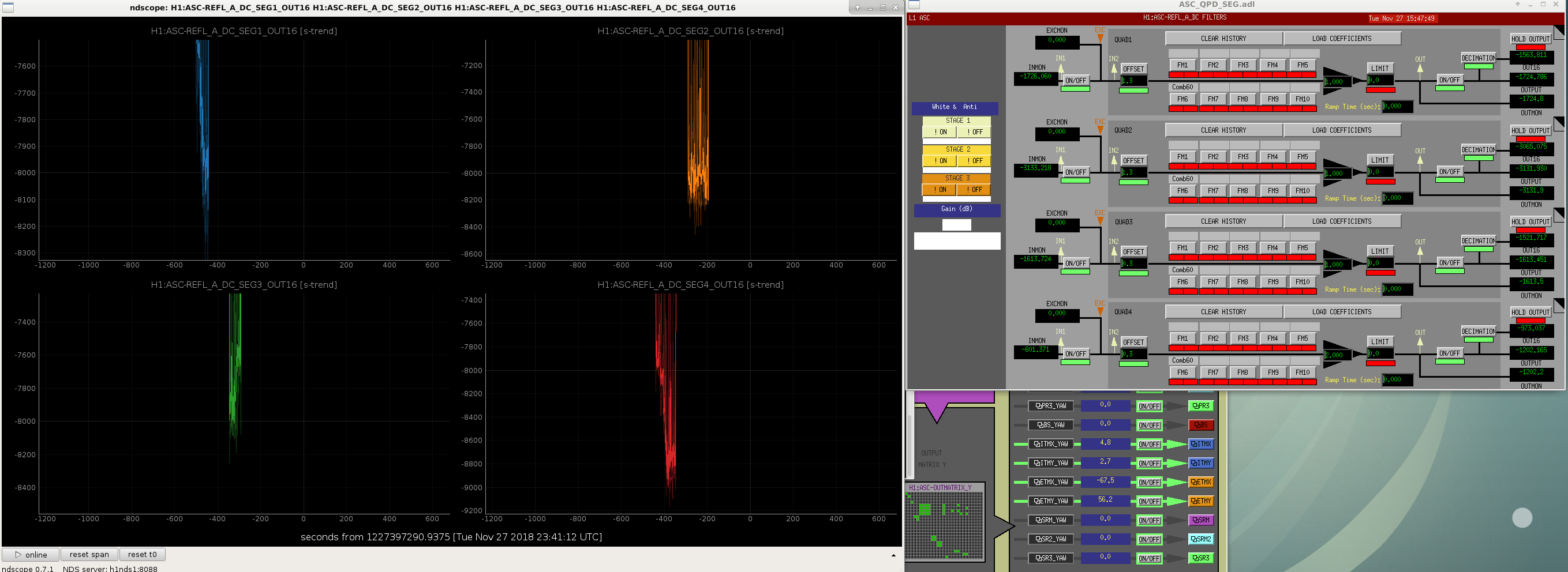
I checked if the ASC REFL_A DC segment 4 problem described above was fixed for good by walking the bean on the WFS using RM1 from one segment to another so the beam is contained by only one of the four segments. At first I was glad to find that the problem was gone (SEG1, 2, 3 and 4 showed about 8200, 8300, 8100 and 9000) but later found that the digital gain of 2 was somehow put back in after our work in the above alog.
This means that the problem came back after we thought that we fixed the problem.
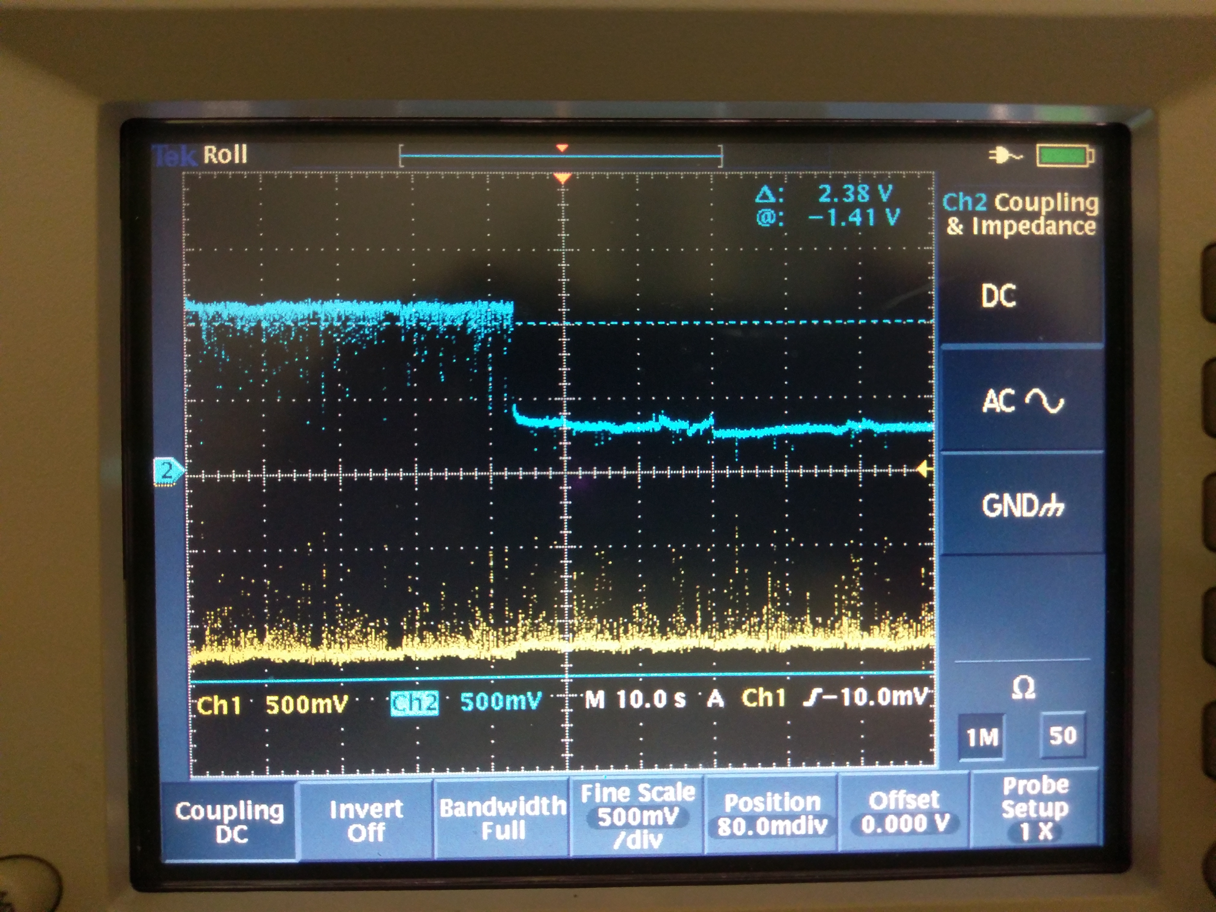
During the EQ this morning I went to the floor and checked the analog signal. I switched the DC interface off, waited for a minute or so, and turned it on.
At first both legs of the H1:ASC-REFL_A_DC_SEG4 were active, but after a minute or so the negative leg failed (attached).
(Sorry that "negative" leg which is a cyan trace is physically positive and vice versa, this is consistently so for all LIGO WFSs. For the record I'm measuring pin 4 relative to pin 15 in ch1, and pin 12 to pin 15 for ch2, see D1300467.)
I also observed a behavior after a longer "cool off" of about 10 minutes that the output switches between good and bad states several times before finally settling down to bad state.
Looking back at my alog from 2014 (alog 14017),
"However, it's not totally impossible that the feedthrough is OK but the seg4 in-vac circuit works only for a few minutes after it is powered on because of slowly developing oscillation or thermal problem or whatever."
that petty "not totally impossible" "thermal problem or whatever" looks much more plausible.
I am beginning to wonder if somehow this problem is inside the detector.  In series with each of the differential DC outputs there is a 10 ohm resistor.  It is sometimes possible that during manufacture only one side of these resistors is soldered on.  The unsoldered side will initially (weeks or months) make contact, so the testing and casual inspection will not reveal any problem.  After some time goes by, the unsoldered junctions develop oxide layers and eventually open up.  Thermal cycling as a result of powering off the device for a significant time may cause mechanical motion associated with the CTE of the circuit board material which can cause the circuit to once again make contact.  After a heatup period, it might well go back to an open circuit.

Verification of the open circuit can be made by an ohmmeter check of the offending wire while the circuit is powered up.  Unfortunately, this will look the same as a connector pin opening and closing, but there's really no reason for a connector to do this as a function of being powered up and down, so my money is on the detector itself.  The output impedance of the device can be measured while it is in the "working" state, and it should be 10 ohms.  If you measure a substantially higher resistance that eventually opens up, then I would think it's the poor solder joint scenario.