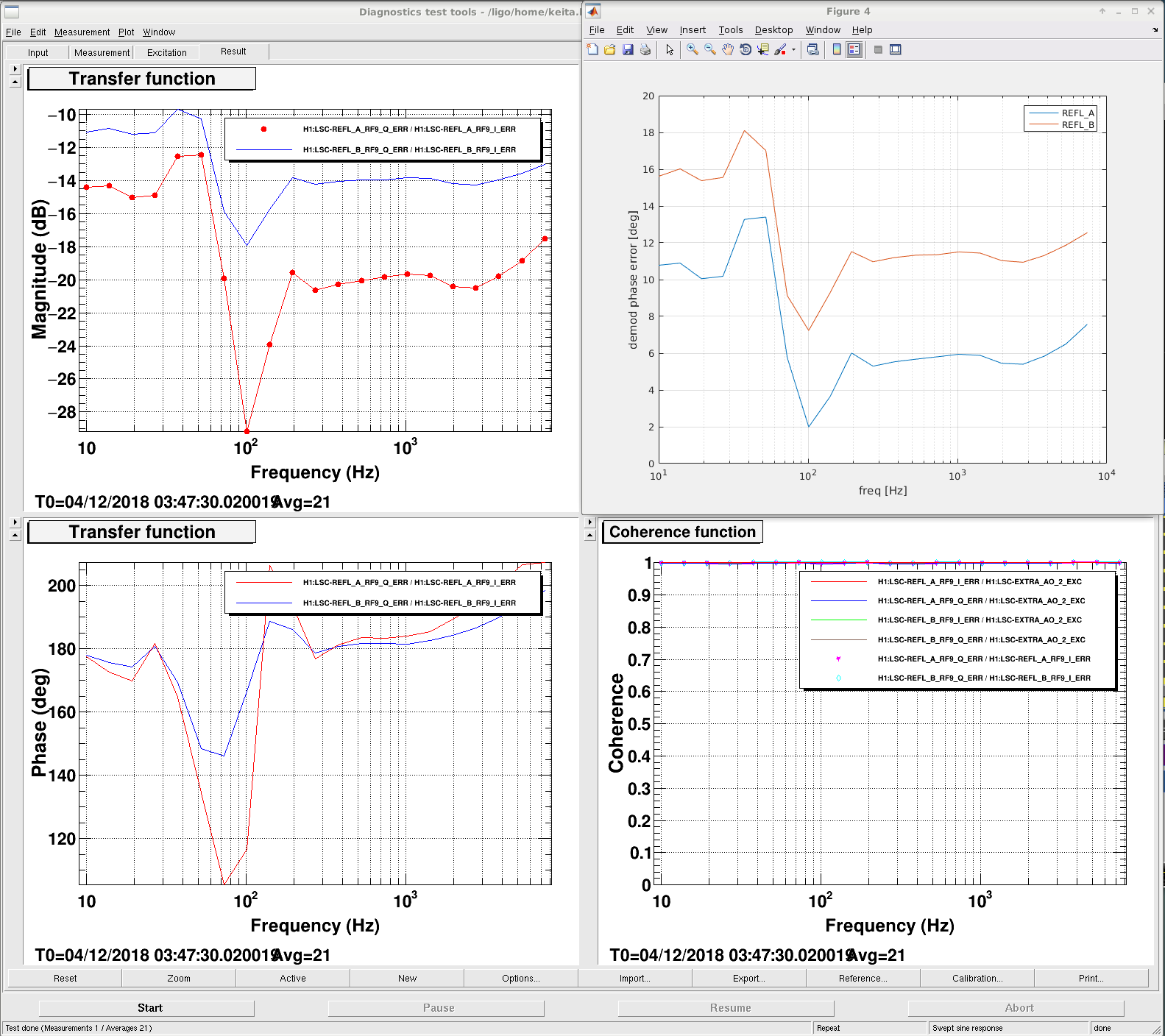
After Fil and I swapped the REFL_B cable (alog 45652) I connected LSC-EXTRA_AO_2_EXC to IFO REFL CM board EXC and injected frequency noise in ENGAGE_DC_VIOLIN (2W) to see the demod phase of REFL_B and REFL_A.
First attachment shows the Q/I ratio obtained from the frequency noise scan. Top right shows the demod phase "error" obtained by p=atan(Q/I). Apparently REFL_A demod phase is decent, REFL_B is not terrible but could be improved.
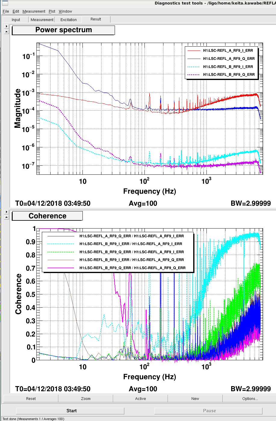
Demod phase error should be flat but it isn't, it seems to cross zero at around 100Hz for REFL_A (maybe the demod phase was set using 100Hz excitation?). HOM or something else, regardless of the cause, this seems to mean that if we optimize the demod phase at f>300Hz there's some I-Q mixing in f<80Hz or so, and vice versa. Since I don't see any real Q signal for f>300Hz but there seems to be some junk for f<100Hz (second attachment), we might be better off optimizing at low frequency.
Not too much low frequency coherence between REFL_A and B, it's not clear if this comes from demod phase difference. Since we're not using REFL_B for control, from this point on we could rotate B phase digitally.
It's also worth measuring this at high power.
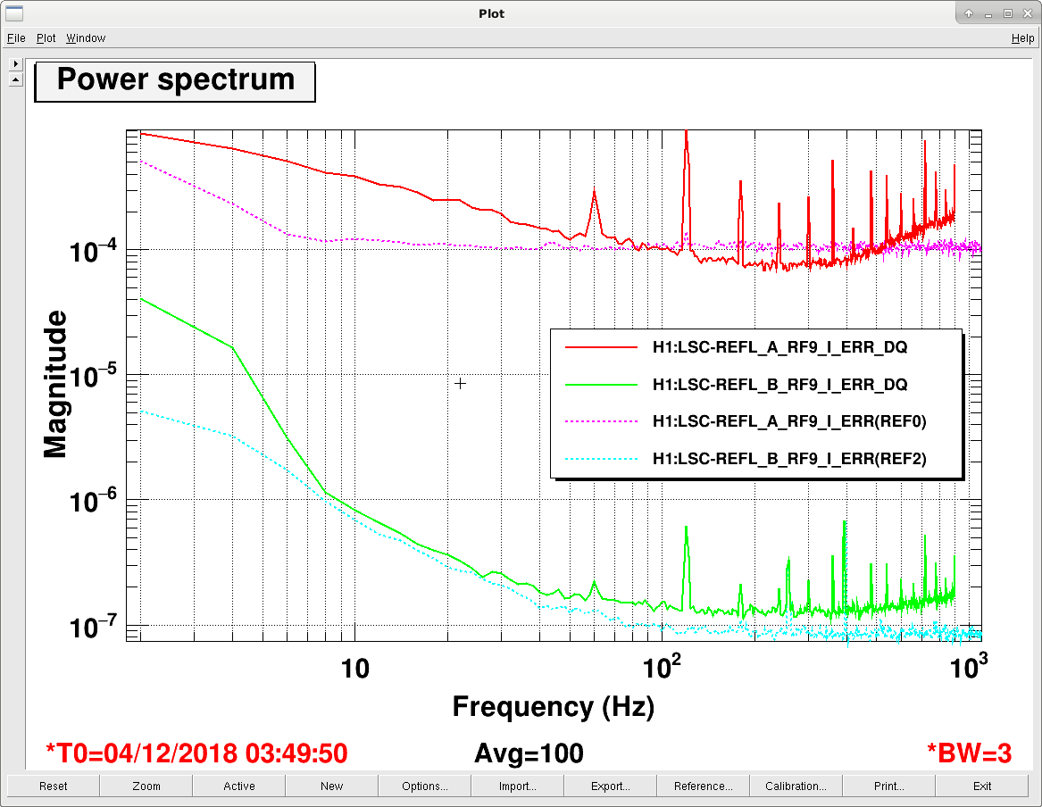
H1:LSC-REFL_A_RF9_I_ERR isn't a particular good witness of frequency noise, see alog 45157. H1:LSC-REFL_B_RF9_I_ERR_DQ seems even worse. Not enough whitening? Slew rate limitations?
OK, indeed REFL_B_RF9_I (green) is limited by the dark noise level (cyan), REFL_A_RF9_I (red) is not as bad as REFL_B but not that great either. At least for REFL_A we can increase the whitening though we might saturate Q phase. These are just readbacks.
Demod phase frequency dependence I don't understand.