
Summary:
We were able to lock the squeezing angle using the 3MHz signal from the OMC DCPD's, and we have caused a few lockloses. We have found that our locking scheme is introducing a lot of noise, so our next step is to lock the OPO length to the laser frequency.
Locklosses:
In our first attempt we used the interferometer locked at 2W DC readout to look for the LO error signal. We caused a lockloss then, and so we then changed to working with the interferometer locked on RF and the OMC locked. We caused a couple of other locklosses this afternoon, one when the interferometer was locked on RF and the OPO became unlocked with the beam diverter open. After this we added closing the beam diverter to the OPO guardian DOWN state, and the state CHECK_EOM (which we enter when the TTFSS EOM is railed).
After successfully locking the squeezer angle, we transitioned to DC readout. When we attempted to close the beam diverter we lost lock, which we also don't understand.
We have been injecting ~10uW of CLF (measured on SQZT6), which gives us about 10 dBm of RF on the 3MHz demod. We are wondering if this is too much and might be part of our lockloss problems. We tried reducing it by a factor of 2.
Locking:
Nutsinee will post details of the squeezing angle lock configuration that we used tonight, even though we don't plan to keep using this scheme.
The basic steps:
- allow the laser temperature servo to bring the beatnote close to the correct frequency. (OPO guardian in down state)
- Lock the squeezer laser to the OPO using the TTFSS (OPO guardian to OPO_LOCKED_CLF)
- Lock the CLF using it's guardian.
- We then could see that the frequency of the 3 MHz sidebands were not quite right. We wrote an epics servo, which zeros the difference between the squeezer vs PSL sample (ref cavity) beatnote and twice the IMC VCO frequency, using the timing system frequency readbacks (which update once per second). This is currently in the guardian called SQZ_PLL in a state called CHECK_BEATNOTE_2, but it will be moved somewhere else and given a more descriptive name. This can hold us within 100kHz of the correct frequency.
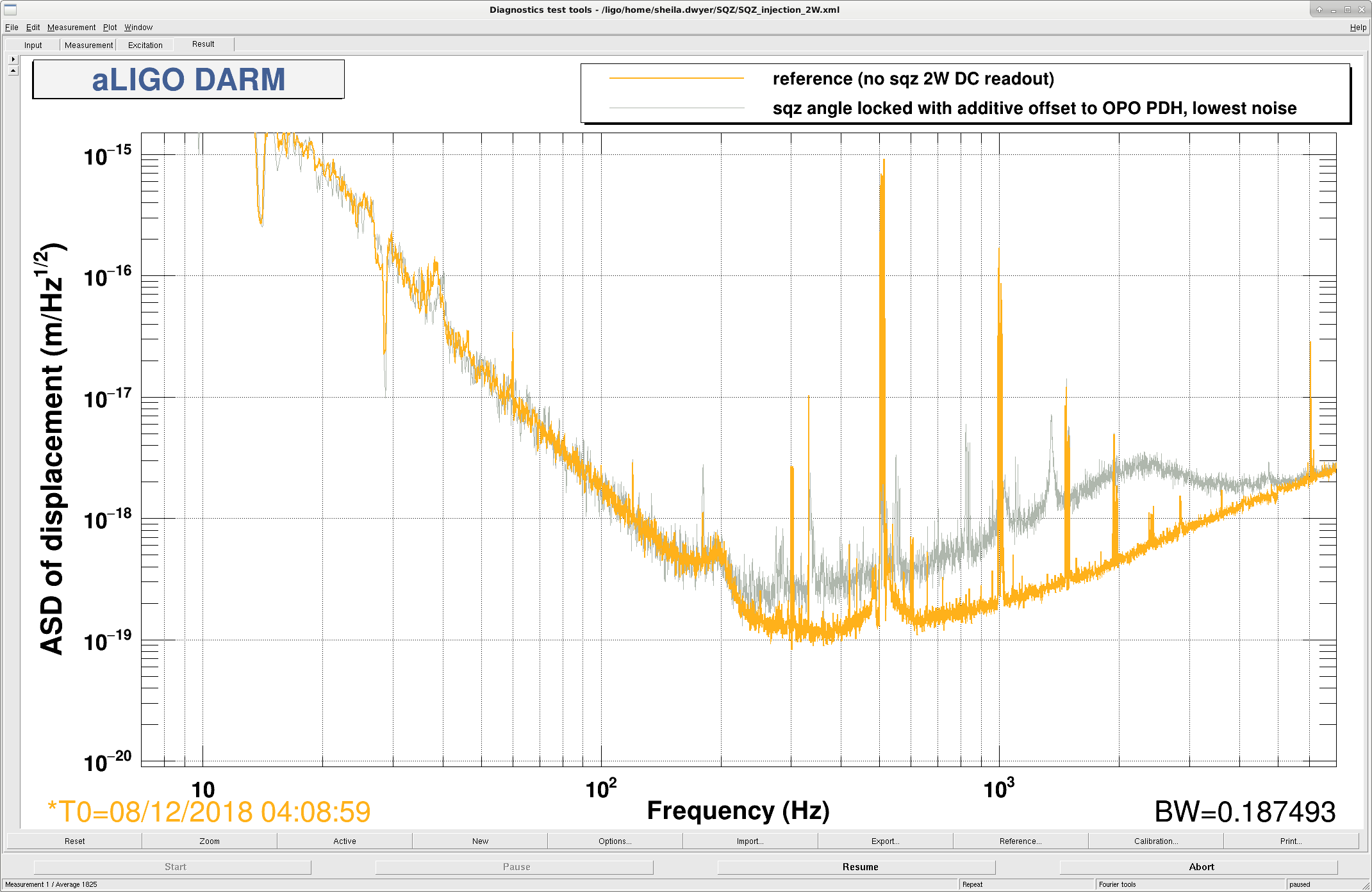
- We sent the 3MHz signal to both the OPO PZT and the additive offset of the TTFSS. The additive offset was needed because of a large peak in the noise at around 1 kHz, which is similar to what was seen with the homodyne locking. Because our locking scheme where the laser follows the OPO (rather than the other way around) introduces a lot of noise, especially at high frequencies, we have a lot of phase noise which means that we need a bandwidth higher than we can get with the PZT only to lock the squeezing angle. For this reason we introduce an offset in the OPO PDH locking, which allowed us to lock but is obviously terrible.
- Injecting squeezing in the IFO with this situation resulted in adding a lot of noise. (See first attachment)
Uncontrolled squeezing:
- The interesting thing is that when we left the beam diverter open but blocked the CLF field and let the squeezing angle rotate, it actually rotates slowly and the large added noise is gone. The second attachment shows the same reference as the first, but with two traces captured with 4 exponential averages at 1Hz, 75% overlap, one showing close to the highest noise that we saw and one showing close to the lowest noise that we saw. This seems like squeezing and anti-squeezing based on how flat the noise is, but there are two things that are surprising. While it might be possible that this isn't anti-squeezing at all, it continued for more than 10 minutes without drifting away. (We were sitting with CLF blocked and the beam diverter open from 4:45 to 4:55, with the OPO locked and the slow servo keeping it's frequency approximately correct.)
- The level of anti-squeezing seems too high. Looking between 1100Hz and 11400 Hz, this is almost 17dB of anti-squeezing. Nutsinee measured the non linear gain to be 3.6, so with our expected total efficiency of 80%, we would expect at most 8dB of anti-squeezing. (I know, this sounds like I am making a factor of 2 mistake, but I don't think I am. I'm attaching the dtt file and my script in case anyone wants to double check.) You might think that the extra noise we see is just some additional noise that we are adding with the squeezer other than anti-squeezing, but at times the noise level drifts down to just a few dB above shot noise.
- This squeezing angle is rotating slowly. With a nonlinear gain of 3.7 and the efficiency of 80%, this would mean that over the 2 seconds of the low noise measurement the squeezing angle only rotated by about 610 mrad, which would be about 100nm of path length change. We should compare this with the calibrated squeezing angle error signal which Nutsinee will post, but it seems strange that we needed 10's of kHz bandwidth to lock the squeezing angle with such a slowly drifting system.
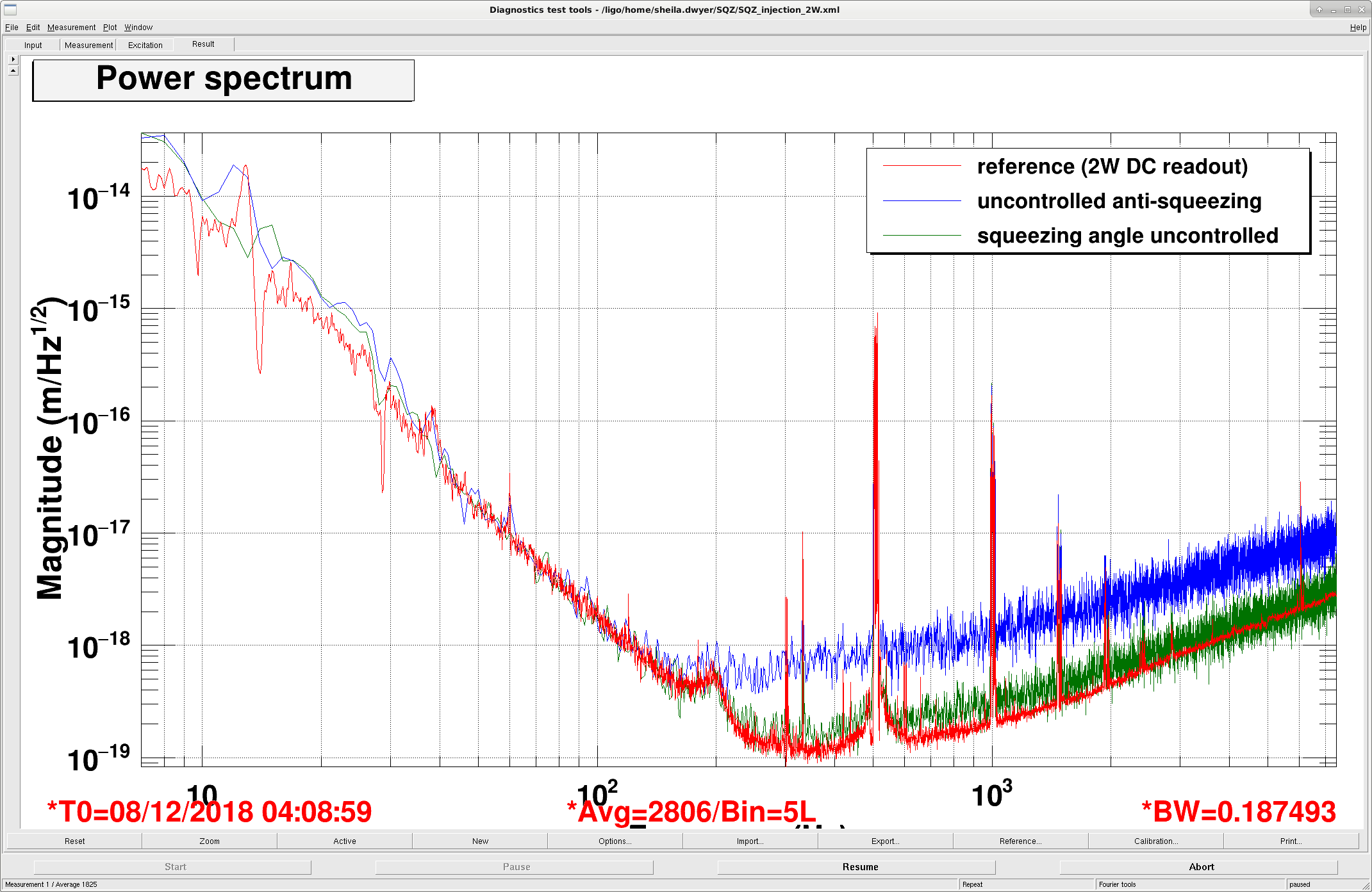


I am not sure what the free-running plot represents. In this case, the 2 lasers differ in frequency by as much as tens of kHz. This would completely invalidate the correlations that are responsible for squeezing. Every now and then the frequencies will cross and one might catch a short glimpse of (anti) squeezing.
The first plot is somewhat of a mystery too. If we really suffer from excess phase noise (as we have measured), why doesn't it effect squeezing at all frequencies? Could it be seeding through the CLF instead?
For reference, at LLO the nominal CLF power (measured on SQZT6) was 50 uW, tests up to 200 uW didn't show a large amount of seeding ( LLO log 41270). So, in principle 10 uW should be well below the seeding threshold.
On the other hand, some "seed hunting" on the double AOM path on ISCT6 was done before injection in the intererferometer, see for example: LLO log 37945 . I don't recall if you have done a similar characterization at LHO.
Lisa- no we haven't done any seed hunting here.
Daniel- I agree that it isn't clear what is happening without the CLF injected, especially since the level of anti squeezing is way too high.
The 10µW is measured transmitted by the OPO, I believe the 50-200µW at L1 are incident to the OPO. The CLF LO signal is fairly high with ~6 dBm (in the quad phase) when we are locked.
So, about the CLF power: all of the numbers reported in the LLO log so far quote the CLF power as measured on the CLF REFL diode, so BEFORE entering the OPO. The OPO has a 4% transmission for the 3 MHz - so indeed the 10 uW quoted for this LHO attempt, measured AFTER the OPO, are 5 times higher than the 50 uW used at LLO, since 50 uW * 0.04 = 2 uW of CLF AFTER the OPO. So, as we all discussed today, the first test would be to lower this power and see if the extra noise is caused by that.