jeffrey.bartlett@LIGO.ORG - posted 11:34, Tuesday 11 December 2018 - last comment - 07:54, Wednesday 19 December 2018(45840)
ITM Photos
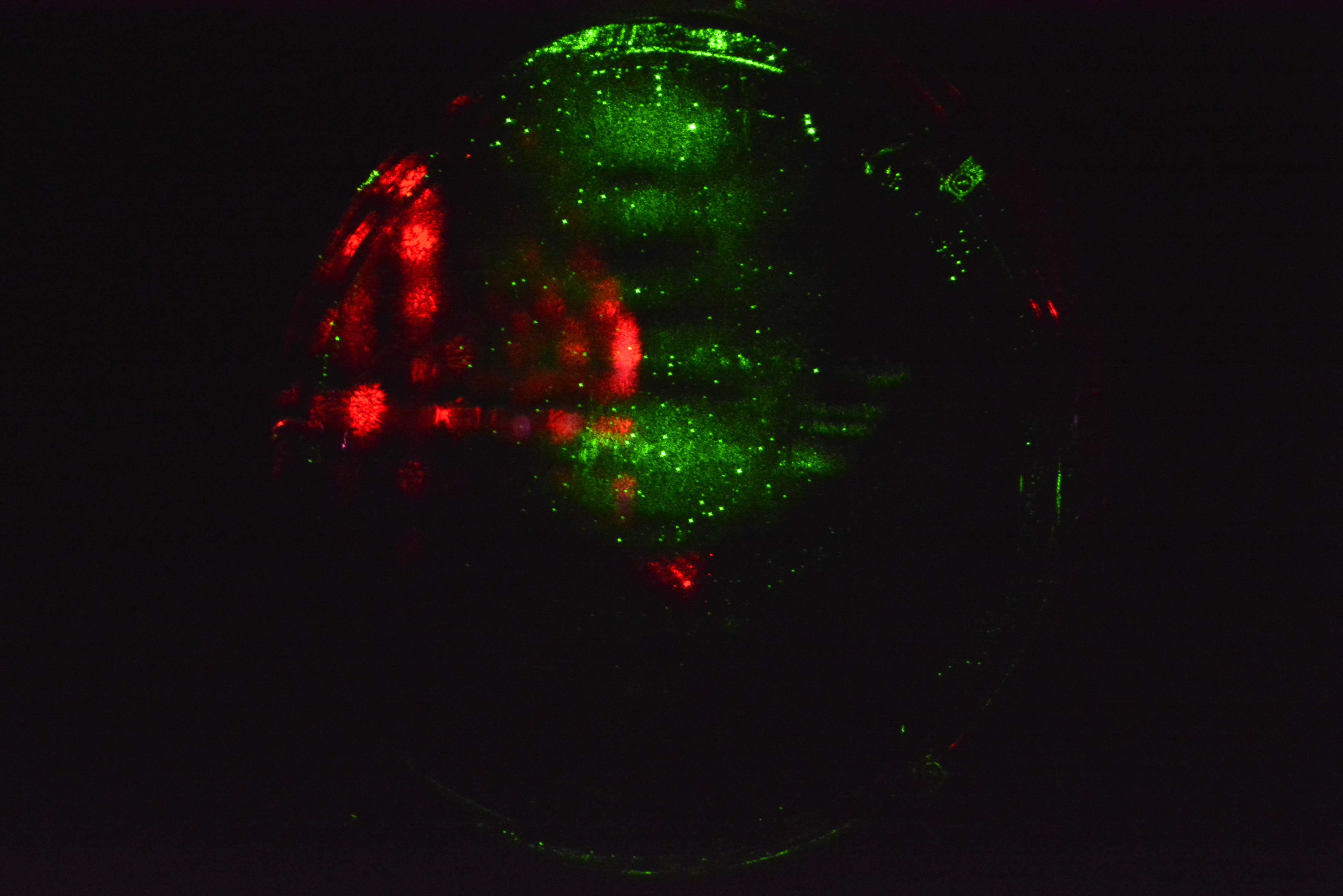
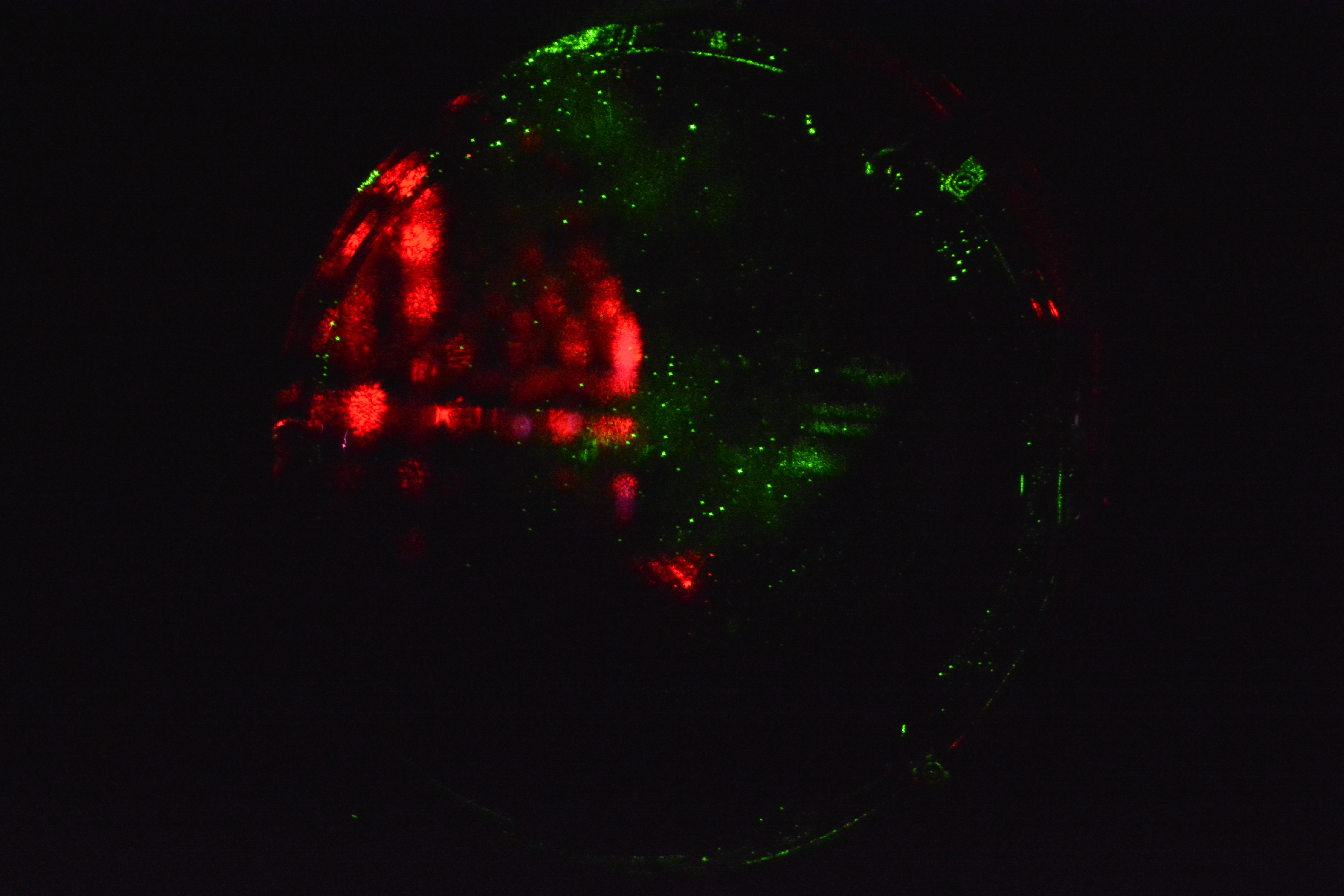
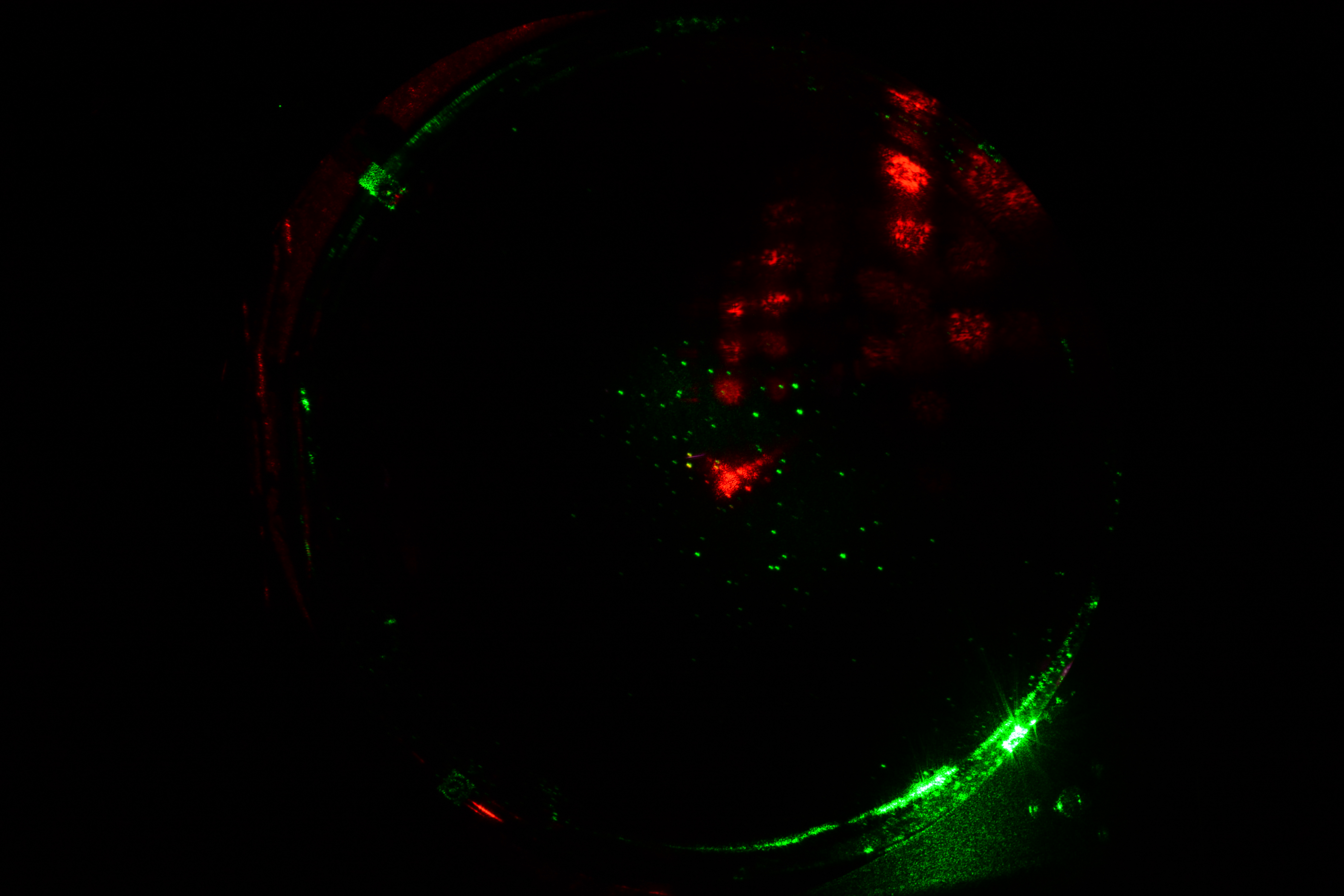
Took pictures of face of ITM-X and ITM-y under green light as the IFO unlocked while setting up. Will try to get a set of shots under IR at at least 20W before the holiday break.
There are two shots of each optic at different exposures and focus points.
| Optic | Frame # | Shutter | ISO | Focus |
|---|---|---|---|---|
| ITM-Y | 111 | 1.0 sec | 6400 | 1725 |
| 112 | 1.6 sec | 6400 | 1725 | |
| IYM-X | 110 | 3 sec | 800 | 1745 |
| 117 | 3 sec | 800 | 1625 |
Images attached to this report

Comments related to this report
to do precise image subtraction in the future (to detect small movement in the point scatterers) we would like the camera position to remain the same. It would be nice, therefore, to design a camera holding jig that would get us back to the same place w.r.t. the viewport. Would be easier to make that analysis quantitiative this way rather than do a lot of image scaling/aligning with camera at different positions.
   Rana, Very good points.

   The camera/lens assemblies are bolted to the Viewport Camera Housing (D1500073), which allows for positioning the cameras. This assembly is attached to the viewport on the Spool Flange via the Viewport Guard Assembly (D080367). This provides a rigid and locked positioning of the cameras. The whole mounting assembly is then covered by a light and dust proof housing.

   The cameras are controlled, focused, and fired remotely, so there is no touching of the actual camera assembly. Unless the system is disturbed is some way the image should not shift in the frame. Also the edges of the baffles and the EQ stop mountings are present in the image, which should provide a fixed point of reference.

   These are just being deployed and any input to make the system more useful would be greatly appreciated.