craig.cahillane@LIGO.ORG - posted 06:01, Tuesday 11 December 2018 - last comment - 13:40, Tuesday 11 December 2018(45831)
DARM offset vs Frequency Noise
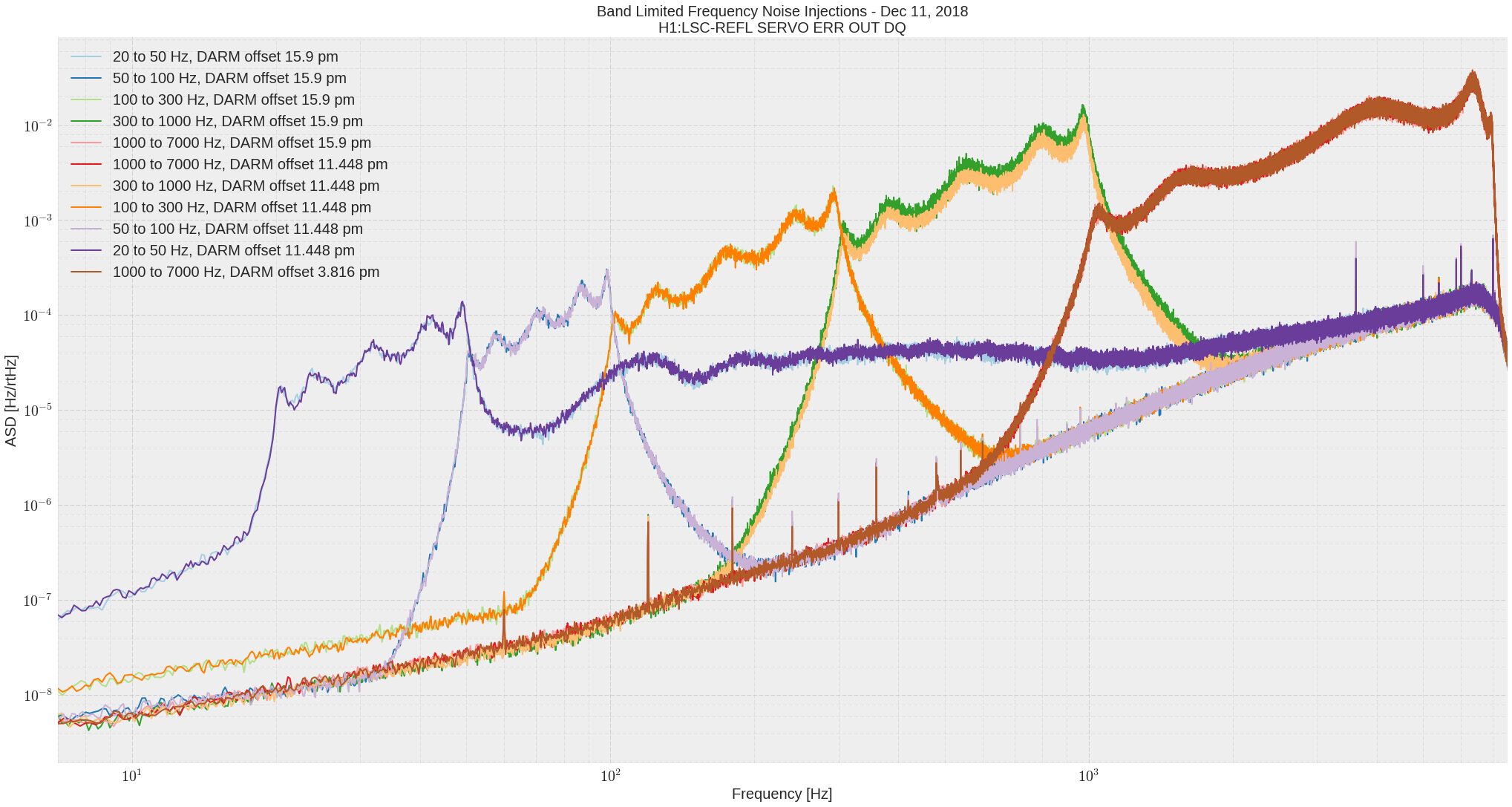
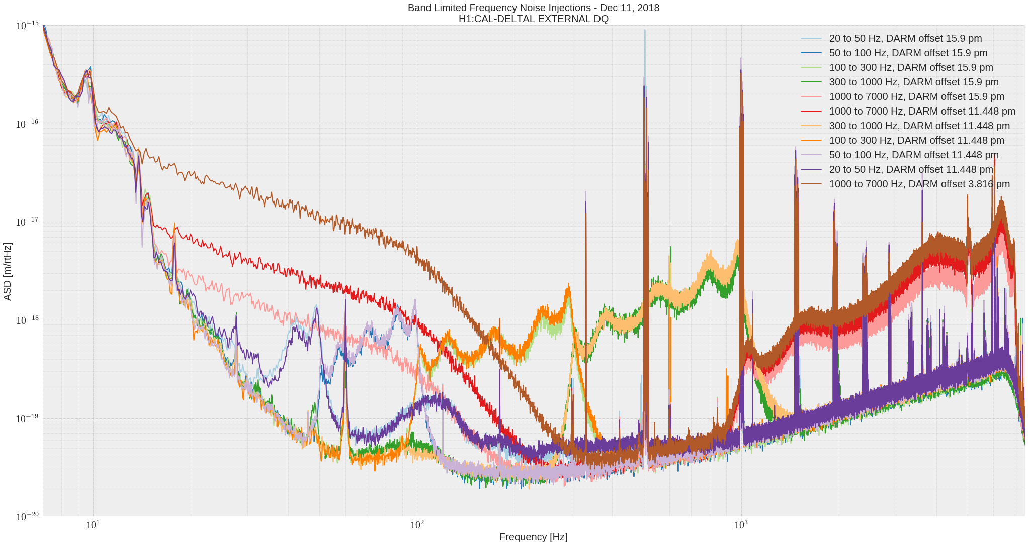
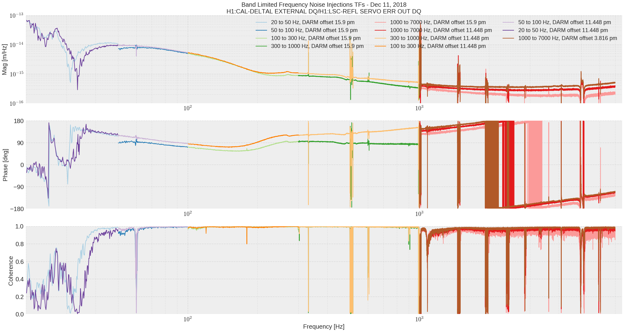
This is a follow up on 45768.

I plotted the TF from frequency noise to DARM with different DARM offsets from two nights ago in hopes of understanding our high-frequency frequency noise to DARM coupling.  This has only raised more questions.
Our freq to DARM coupling appears to be moving at both high and low frequency by about a factor of 2 on the order of 5 minutes.  Unclear why.

Some details about the measurements:
REFL SERVO ERR Calibration
(the ADC and whitening gain of 200 are accounted for in the filter module now)
--------------------------------
SumNode = dB2Mag(8.0) # V/V
REFL9Trans = 2900. # V/W
REFL_A_B_BS = 0.5 # W/W, half light on REFL A
CARMgainDC = 15.5e-3 # W/Hz
CARMpole = 0.6 # Hz

Injection Time per Measurement: ~200 s

The measurements were not really taken in a sensible order, I took the 15.9 pm offset measurements all first, then the 1000-7000 Hz 11.4 pm meas, then the 1000-7000 Hz 3.8 pm meas, then the rest of the 11.4 pm. I mention this because the freq to DARM coupling seems to change more with the time the measurement was taken than anything else.

Questions
1) The linear coupling appears to change significantly between measurements.  While the DARM offset changes may be able to explain some of the coupling change, there are swings completely independent of the DARM offset.  These measurements were taken ~two hours after we had locked at 20 W, so the swings are probably not thermal either.
2) There are changes in the linear coupling at both low and high frequency.  The low frequency is thought to be dominated by radiation pressure/contrast defect effects.  The high frequency coupling is not understood, and thought to be dominated by higher-order-modes, but we have no theory of this.
3) The nonlinear low-frequency coupling for the 1000-7000 Hz injections is probably due to excess OMC length control sensing noise from the frequency noise.  However, it doesn't decrease fast enough with increased DARM offset.  More data needed.
4) These injections used an elliptic filter with 150 dB attenuation.  This was the max attenuation that foton allowed me.  However, I still caused some massive upconversion in the CARM loop when injecting from 20 to 50 Hz.  Unclear why.

Next I would like to do a long-term injection at high frequency and make a spectrogram of the ordeal.  I tried making some spectrograms of these 200 second injections, but was unable to see much change in that time.

EDIT: Question (4)
Images attached to this report
Comments related to this report
When we change the DARM offset we haven't been compensating for the change in the OMC length locking loop ugf.
About the downconversion:
Since the OMC dither uses the normalized DCPD sum, the ugf of the OMC length loop stays the same as the DARM offset is changed. This means that for smaller DARM offsets, the OMC length servo imposes more length noise on the OMC for the same amount of DCPD intensity noise caused by a frequency noise injection.