Saravanan and Shivaraj
Since the installation of new time-dependent calibration parameters tracking model, we weren't able get some reasonable numbers for the tracking parameters (known as kappas) (a-log 45766). One of the main reasons was that we didn't we have good lock stretches with stable IFO configurations to test/debug the model. During ER13, there were a few such good lock stretches so we decided to look at one. Specifically we looked at GPS times 1229132118-600 when all the signal outputs from the calibration TDEP model were almost constant (so that we can concentrate on systematic).
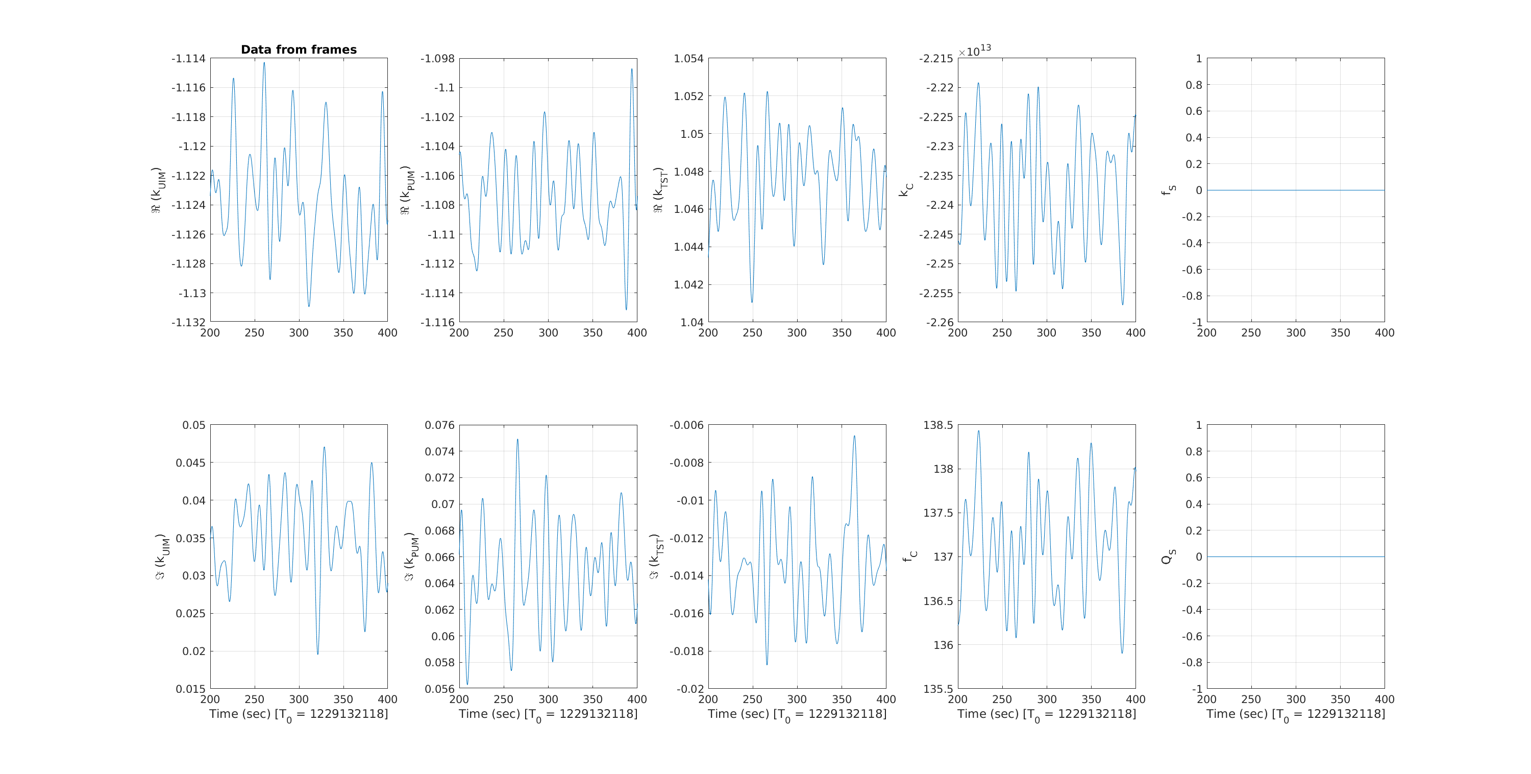
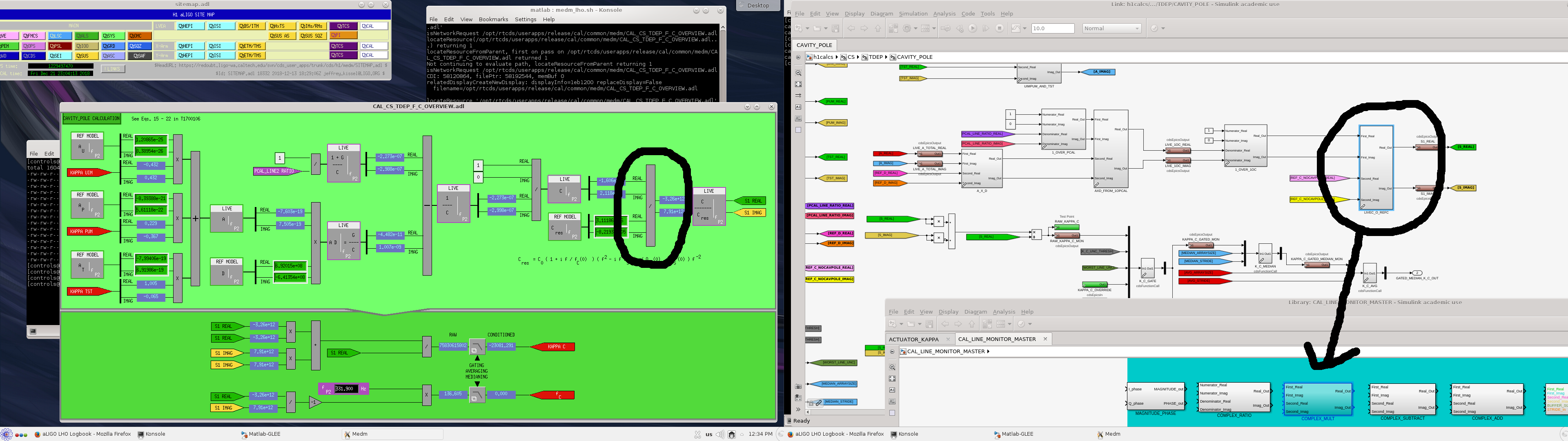
The first plot show the kappas as output by the front-end with then installed TDEP model. We see that kappas that track the actuations change are close what we expect (the signs of UIM and PUM stage were wrong though, they shouldn't be negative) but kappas that track the open loop IFO response are very different than what we expect. So we looked at the signal flow in the TDEP calibration model. To understand and compare what we would expect for signals at different point of TDEP model, we wrote a matlab code mimicking the signal flow. This code is similar to PCalmon we used to run during O1 and O2, but this code's output is continuous as front-end and uses the same filters as front-end (loaded from front-end model). This way we can calculate what we expect for signals at different points of TDEP model and compare against what we see. Looking at this code's output and TDEP model we found that the final complex blocks in TDEP model for IFO response (coupled cavity and spring) were supposed to be complex division but the installed ones are complex multiplication. Second figure show the MEDM and simulink model with the block circled for coupled cavity part. Same thing applies for the optical spring part.
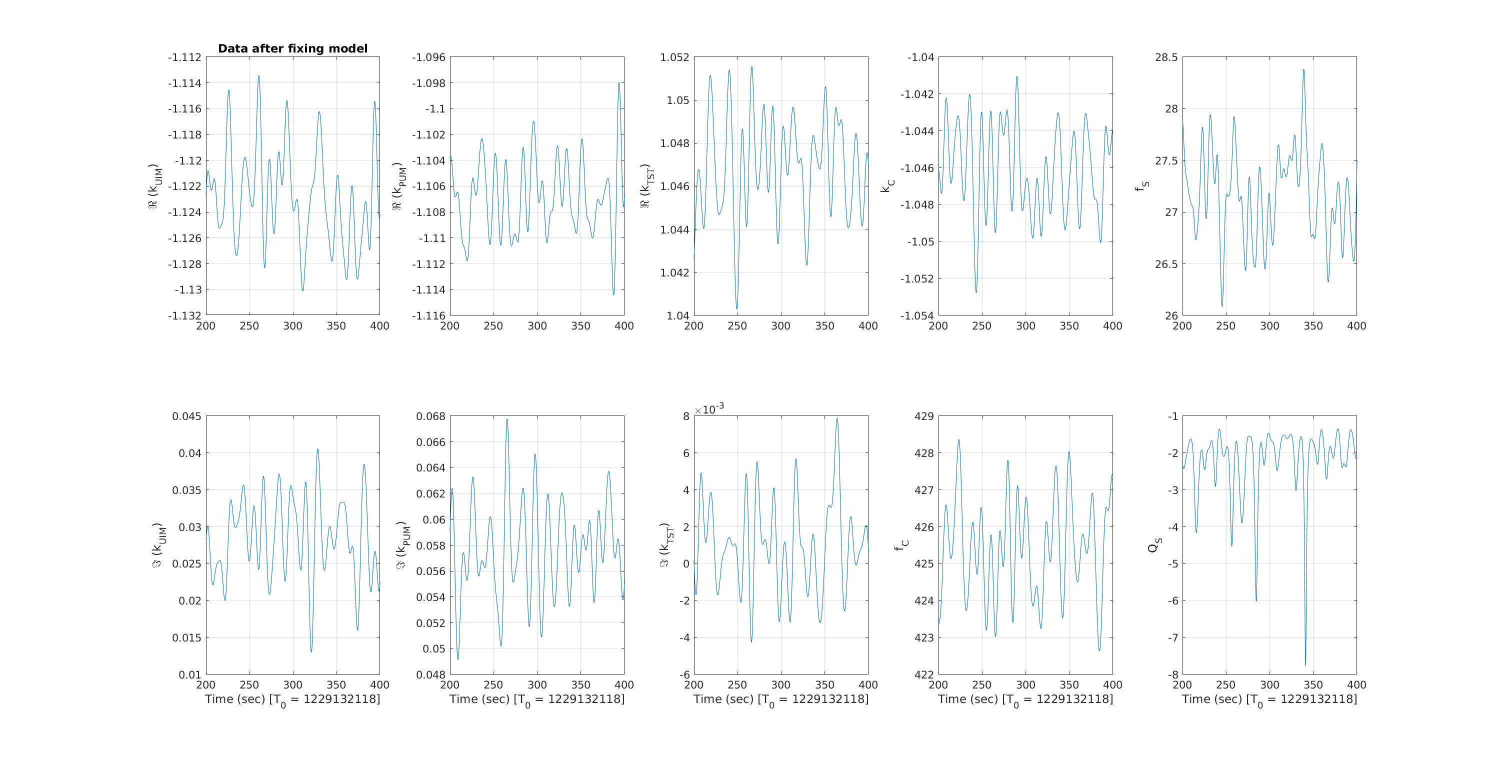
The advantage of the matlab script is that we can regenerate the data with any changes. The last figure show what we would have seen if the last block was correctly installed as complex division. We see that the IFO response part would have come out as okay-ish. However the sign of optical gain is negative which is not correct and the optical spring parameters are not quite what we expect. If we change the sign of EPICS parameters EP2, EP3, EP4 installed via a-log 45766, then the actuation and coupled cavity pole parameters all come out okay (proper sign and magnitude similar to what we expected). But the spring parameter values still stay the same i.e., bit off then what we expect. We will try to further debug this, but at this point it would be better to do a full set of calibration measurements in a good low noise stable to build a new model. Since the UIM and PUM stage kappa values are nearly 10 % off of the initial model values, may be something not quite right in the current model (during the whole of O2, the kappa_pum hardly changed by a percent which is what we expect). Also at this point it would be good to move the lines to its final configuration.
The matlab script used for the comparison is added to svn at,
aligocalibration/trunk/Common/MatlabTools/calcsTools/calcsTDEPMatlab.m