As Danny reported on Friday 46382, the HAM2 motion coupling to DARM that Robert noticed 46373 is coupling through the ISS second loop, and there is also strong coherence with DARM below 30Hz.
Dany and I used data from several different locks on Friday, and we couldn't make a good comparison of the low frequency noise in DARM because some of those locks had large scattering or other low frequency problems. This morning Keita Jenne and I got about 10 minutes of data with the ISS second loop in 4 different states while the interferometer was in low noise:
| second loop off, output switch on | Jan 14th 2019 18:38 UTC |
| second loop off, output switch off | 18:48 UTC |
| 2nd loop AC coupled | 18:59:30 UTC |
| 2nd loop DC coupled | 19:17 UTC |
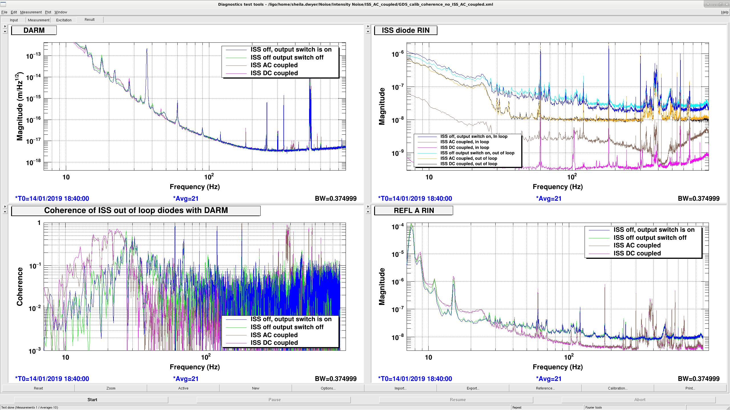
The attached DARM spectrum shows that the ISS was adding noise to DARM both at 25Hz and below and from 350-400Hz. The coherence of the ISS out of loop diodes with DARM is pretty much the same weather the second loop is AC or DC coupled. REFL RIN also indicates that the intensity noise imposed by the second loop is the same for the AC coupled or DC coupled ISS.
Georgia and Danny have pico'd the array to fix this.
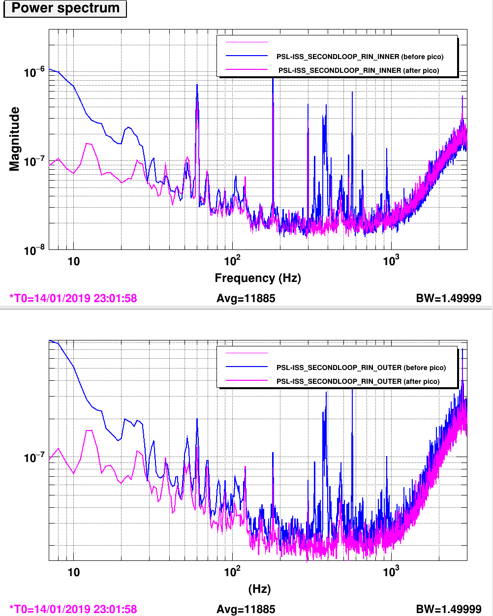
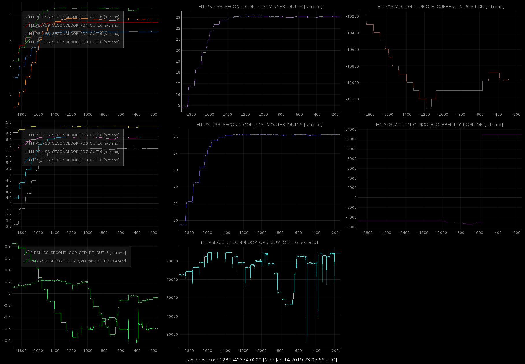
We pico'd onto the ISS second loop QPD and PD arrays. We have improved the RIN on both the inner (in-loop) and outer (out-of-loop) PD arrays (first attachment), and the alignment onto the individual photodiodes and the QPD (second attachment).
Gabriele last centred the beam on the array last year. There are two picomotor mirrors on the path from IM4 to the ISS arrays, we adjusted both PM1 and PM5, but mostly PM1. We did this pico'ing with the IFO unlocked, and the power through the mode cleaner at 30W.
We definitively made the noise better from 300 Hz - 1 kHz, though we noted the peaks around 485 Hz seemed to be breathing a bit. We also noted the 60Hz line appears worse on the inner PDs than the outer, perhaps we could consider switching which is the in-loop sensor.
The second attachment shows time series' while picoing. The first row is the PDs and PD sums for the inner sensor, the second row is for the outer sensor, and the third row is the QPD. The final colum is the picomotor positions, at t = -750 we switched between the picomotors.