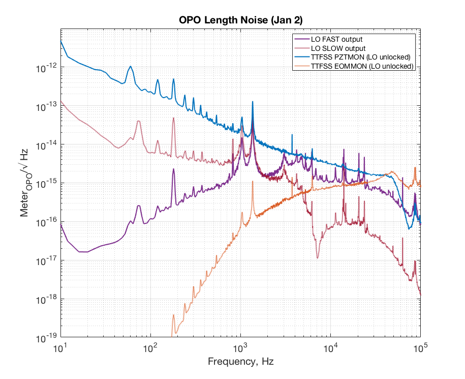
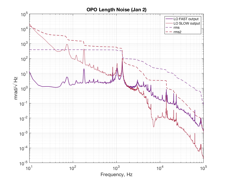
Daniel, Nutsinee
Attached two plots of LO and TTFSS control signal. One shows TTFSS control signal when LO was locked (Dec 27) and the other shows TTFSS control signal when LO was unlocked (Jan 2). Everything is calibrated in green Hz/V (say free-running laser would be ~200Hz/sqrt(Hz) at a 100Hz).
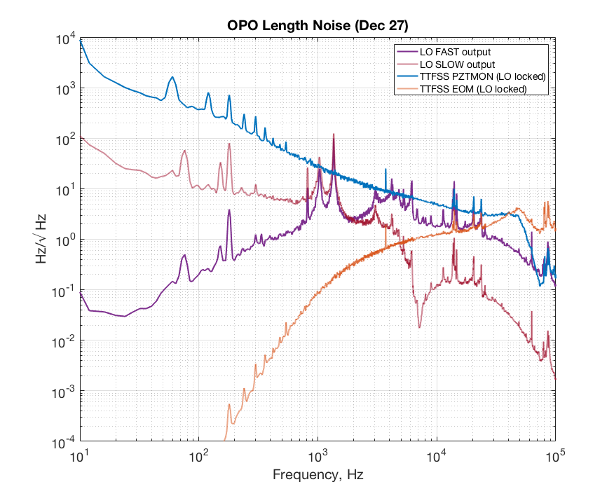
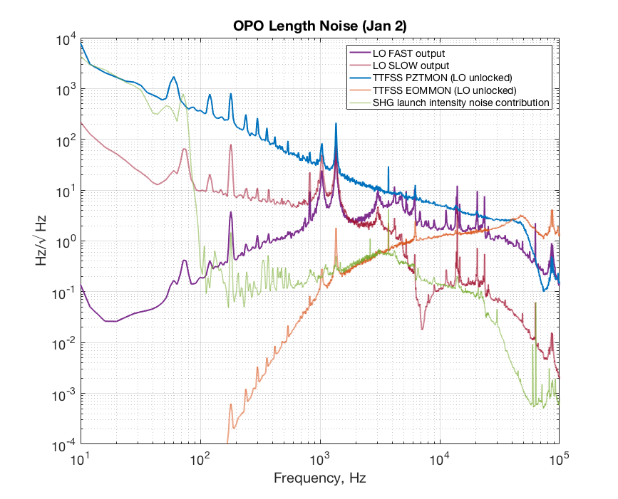
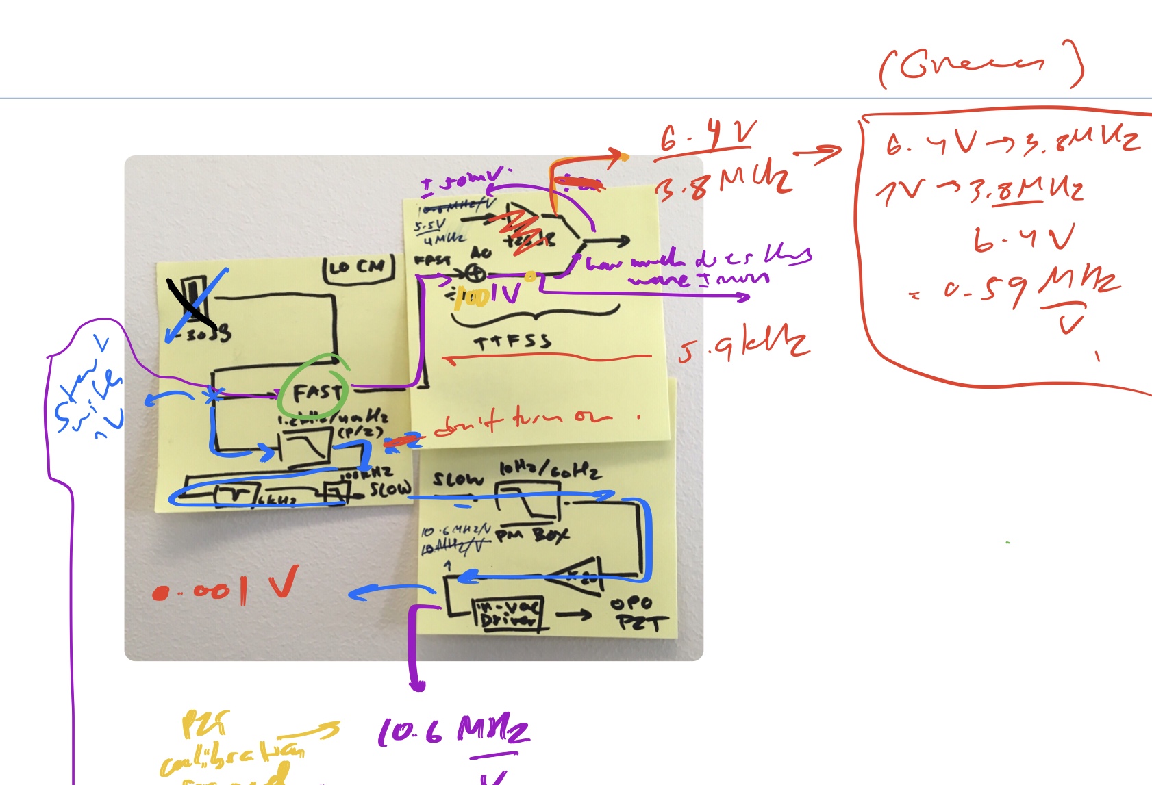
Our scheme makes the laser follows the OPO, thus the TTFSS control signal should see mostly free-running laser noise. And whatever's left is taken care of by LO. Thus we look at LO spectrum for OPO length noise. LO fast signal is fed to additive offset of the TTFSS and slow signal goes to OPO PZT.
The feature at and around 1.4kHz is what we thought might be the actual length noise of the OPO as the line disappear from TTFSS control signal when you turn on the LO loop. But there are lines between 10lHz-30kHz that only shows up on the TTFSS control signal when the LO is locked. Suggested that they are introduced by the LO loop (possibly OPO PZT). Could be notched out. For the rest of the noise, I'm not sure if we know where they came from. Part of it could be PSL LO fiber noise. It'd be nice to compare to a spectrum taken with the OMC.
To get the laser PZT calibration I moved OPO PZT by 0.5 V (corresponds to ~10MHz), looked at TTFSS PZTMON (not /25) and 158MHz beat note. The PZTMON read out is then multiplied by the filters on the interface board to get the actual voltage sent to the laser PZT. The result is 1.7MHz/V (in red).
For LO fast output calibration V/Hz I relied on TTFSS IMON Vpp/FWHM. There's a factor of 100 at the additive offset.
Files in m/sqrt(Hz) and rad/sart(Hz) attached below.