craig.cahillane@LIGO.ORG - posted 17:46, Wednesday 16 January 2019 - last comment - 16:44, Monday 05 August 2019(46483)
IMC REFL and REFL A/B shot and dark noise levels
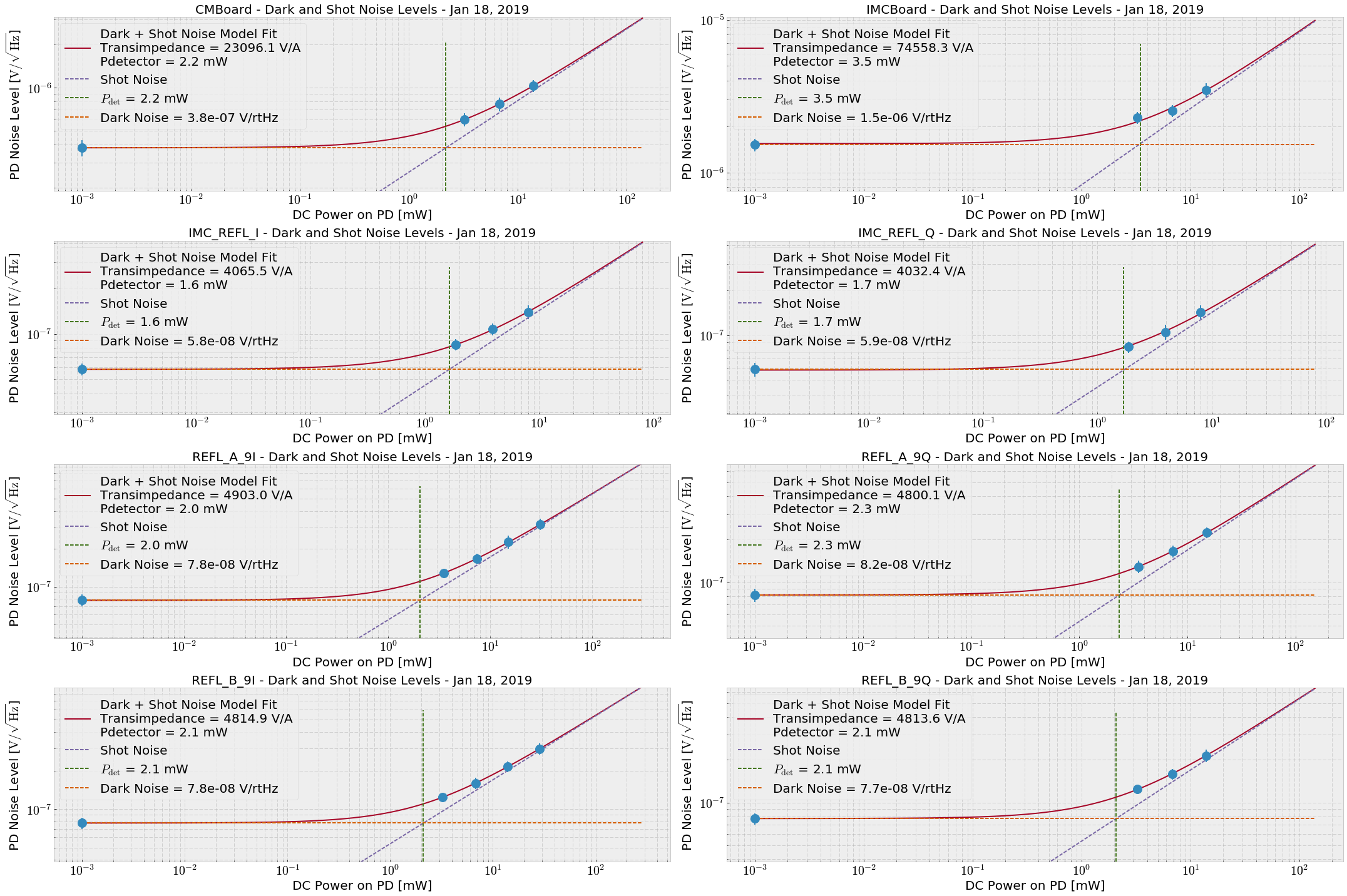
On Monday evening, Koji and I went out and measured the shot and dark noise of the IMC/CARM PDs. Then, Koji taught me how to think about photodiode noise. Slides 35 and 36 of G1401145 Model:where nV is the voltage noise floor, T is the transimpedance, e is the electron charge, R is the responsivity of e λ/(h c) = 0.858 A/W, QE is the quantum efficiency of 0.9, PDC is the DC power from the incident light, and Pdet is the power apparent from the intrinsic detector noise (i.e. the incident power where shot and dark noise are equivalent). We fit the measured shot and dark noise spectra for IMC REFL I/Q, REFL_A 9I/Q, REFL_B 9I/Q, and at the CARM and IMC servo board OUT2 locations with the nominal gain slider settings (OUT2 connected to IN1, CMB IN1GAIN = 6 dB, IMC Board IN1Gain = 28 dB). REFL_A spectra are plotted in attachment 3 as an example. For dark noise I shuttered the PSL. For shot noise I measured with 1W, 2W, and 4W input requested power, and recorded how much light was reported by the LF channels:
Light Level REFL_A_LF [mW] REFL_B_LF [mW] IMC_REFL_LF [mW] ---------------------------------------------------------------------- Dark 0 0 0 1W PSL 3.51 3.24 1.87 2W PSL 7.38 6.80 3.92 4W PSL 15.08 13.90 8.01 Full Lock 4.36 4.02 1.15Then, I found the average noise floors for each spectrum between 3 and 10 kHz, and fit the model to the data. (attachment two) I have let the transimpedance number from the fits capture the servo board gain sliders.Photodiode Transimpedance [V/A] Pdet [mW] IN1 Gain Slider [dB] ------------------------------------------------------------------------------------- CMBoard 730.4 2.2 6 IMCBoard 2357.7 3.5 28 IMC_REFL_I 128.6 1.6 IMC_REFL_Q 127.5 1.7 REFL_A_9I 154.9 2.0 REFL_A_9Q 151.8 2.3 REFL_B_9I 152.4 2.1 REFL_B_9Q 152.2 2.1
Images attached to this report


Comments related to this report
The transimpedance numbers above are incorrect.  In the model I did not convert mW to W for the calculation, so all numbers were scaled down.
Posted is a corrected plot.
Images attached to this comment
Comments from Daniel

"... the transimpedance typically describes the electronics gain. However,
yours doesn't. The shot noise eq is missing a sqrt(2), and the demod will fold noise
below the LO and above the LO on top of each other, which results in another sqrt(2).

So, your T is twice as large as the electroncis gain. For IMC REFL the mesured RF gain
of the PD is 353 Ohm, the demod gain is ~5.4 which gives 1.9k."

Essentially, the above model ignores a overall factor of 2, and collects the demod gain of 5.4 into the transimpedance, which is not correct.

So, for IMC_REFL_I above, the transimpedance is actually 4065 / 5.4 / 2 = 376 ohms, close to the direct measured 353 ohms Daniel reports.
REFL_A_I transimpedance: 4903 / 5.4 / 2 = 454 ohm
REFL_B_I transimpedance: 4814 / 5.4 / 2 = 446 ohm