I spent more time looking at the HAM3 ISI yesterday, trying to figure out the source of the 1.1 hz peak. I don't have a fix, or even an improvement, but I think the V2 GS13 is probably bad.
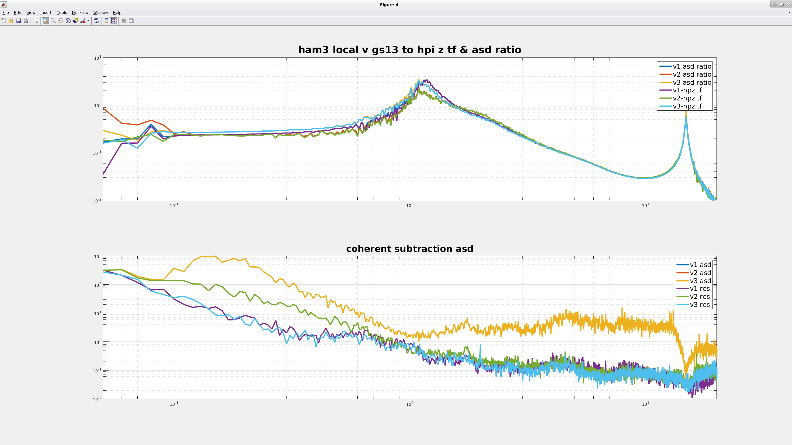
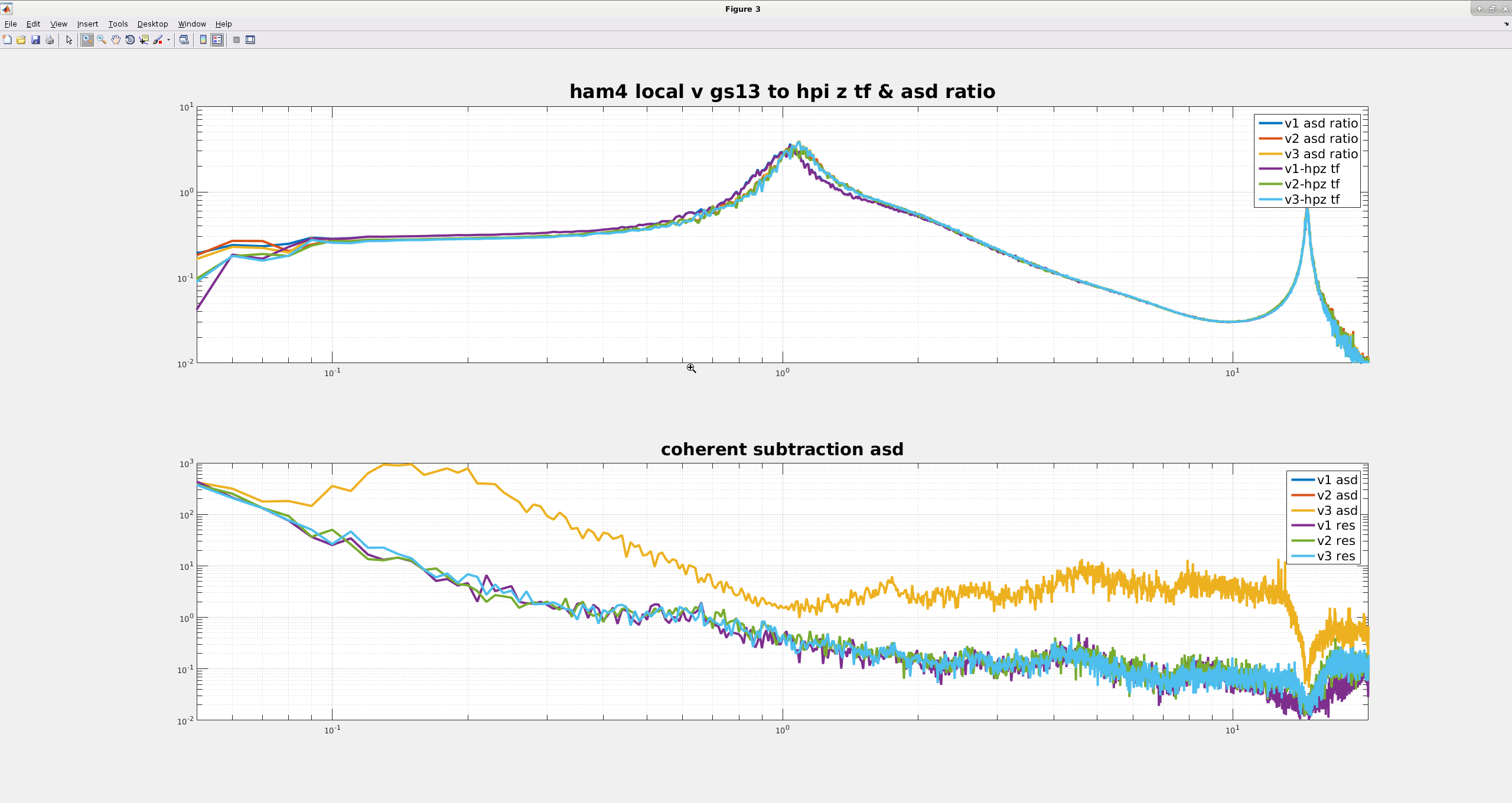
The top plots on my first two attached images compare the HAM3 & 4 HEPI L4C Z to local ISI GS13 asd ratios and transfer functions, HAM3 in the first image, HAM4 for the second. For all of these plots, both ISI's were damped only, so only the GS13s were in loop at the time. For both chambers, it's hard to see, but the HEPI Z to ISI V1/V2/V3 GS13 asd ratios lie right on top of the equivalent transfer functions. If I remember what Jeff said right, this means there are no significant non-linear cross-couplings in the GS13s. Note, also that the HAM4 tfs all look about the same, but V2 for HAM3 has a lower Q and generally doesn't look quite as similar to the other two HAM3 sensors, just like Keita found a couple months ago.
The bottom plot for the first two images are asds for the HAM3 and HAM4 local GS13s. The gold line on each lower plot is actually 3 lines, the asds for each of the individual GS13s on the table are very similar over this frequency range. The light blue, dark blue and green (?) traces are are the residual asds after using MCCS2 in Matlab to subtract all the coherent HEPI Z noise from each GS13. For HAM4, the residuals for all 3 GS13s look pretty similar, but for HAM3 there is quite a bit of extra noise in the residual for the V2 sensor below 1 hz. I'm not sure where it's coming from, but I could believe that it's something like the mass in the seismometer is a little sticky, or there's something wrong with the flexures.
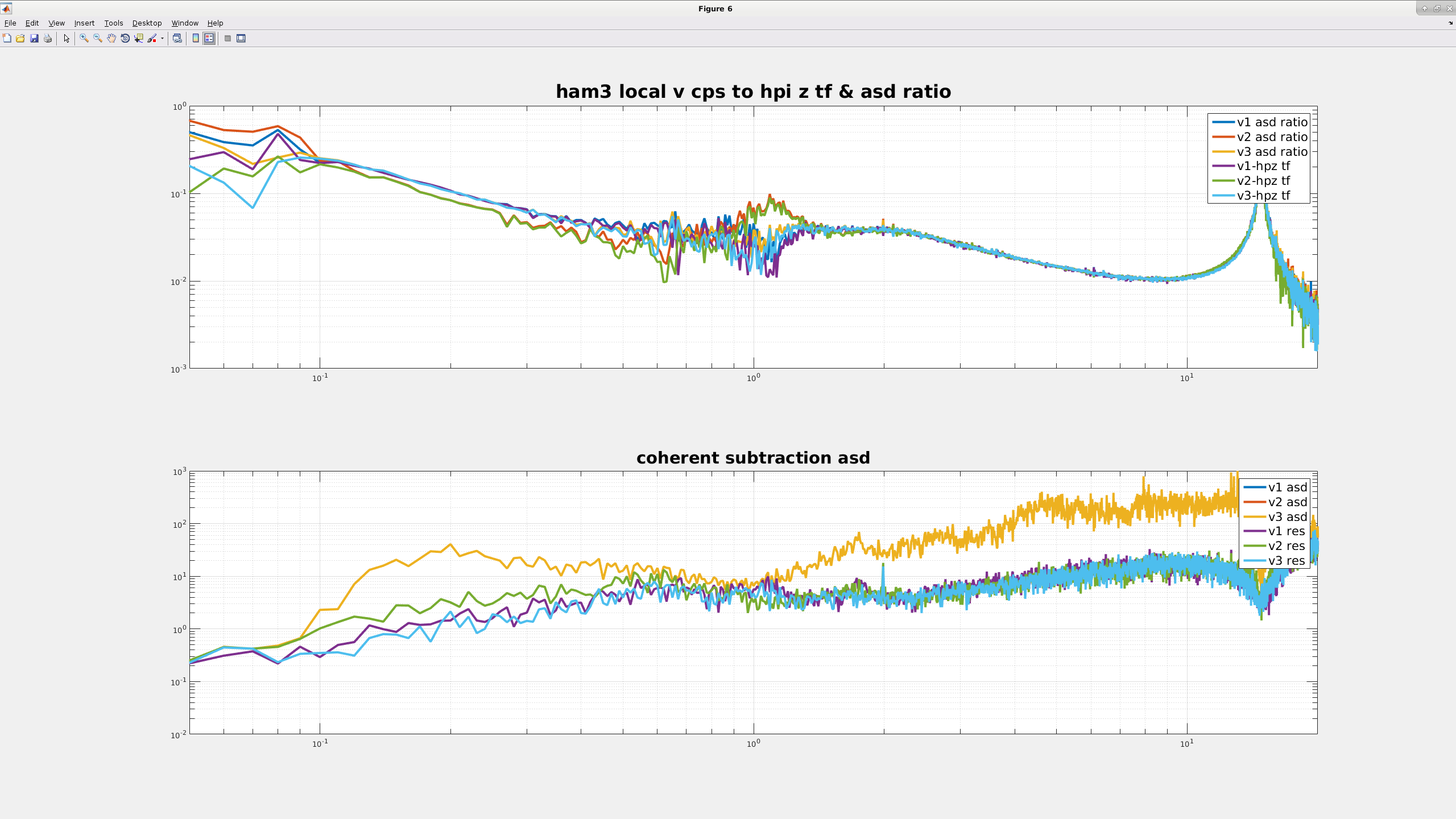
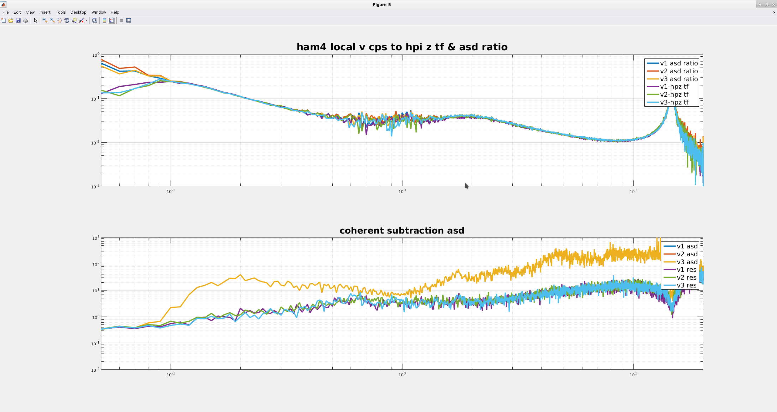
The third and fourth images are similar to the first two, but use the local CPS on HAM3 & 4 instead of the GS13s. The top plots on these images are similar to the first two, the asd ratios mostly lie right on top of the transfer, though match up is not quite as good at 1hz. I think this is probably because the ISIs, GS13s and L4Cs all have modes around 1 hz, there's a lot of stuff happening there.
The bottom plots on the third and fourth images are again the MCCS2 coherent subtraction of the HEPI L4Cs from the ISI local V1/V2/V3 CPS. Again, HAM4 all of the sensors asds and residuals all look pretty similar and the asds for the HAM3 sensors all look the same, but the residuals for the V2 sensor show more noise below 1 hz. I think this is because the damping loops are impressing the extra noise from the V2 GS13 on the V2 CPS. I plan on repeating this measurement for a period when the all of the controls are off, to see if the V2 CPS residual changes.
Some other tests I tried, but generally didn't keep good spectra of:
Moving sensor correction to HAM3 HEPI - no change to the 1.1hz peak, but good isolation at the microseism. Adding an IPS & L4C blend to the HEPI Z loop also didn't improve the peak, but the HEPI Z loop is, I think, only 2 hz ugf, maybe the gain of the Z loop can be pushed up.
Pushing RX/RY/Z blends around, this affects the frequency of the peak some, but doesn't improve the height much.
Turning off the ISI Z loop makes the peak go away. If the 1-10hz Z motion isn't that important, maybe we could run this way. Worth looking at more.
Running the Z isolation loop with just the V1 & V3 GS13s. Again, no improvement, but 4 out of the 5 remaining loops still use the V2 sensor. The contribution is small for the X/Y loops, but RX and RY need the V2 GS13. This is worth looking at a bit more, Brian Lantz has a DCC document about why we shouldn't remove the sensor completely.