Daniel, Nutsinee
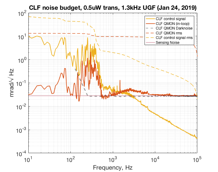
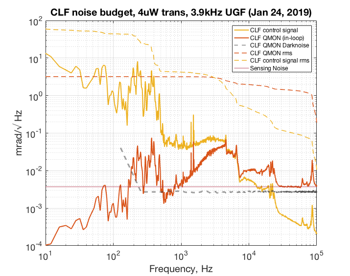
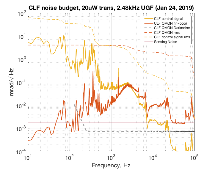
We will later be using this information to calculate the overall phase noise contribution from CLF and what is the best power to operate when injected into the IFO. But for now these plots are just showing noise at various CLF power. At 1X power (0.5 uW CLF transmitted) we are mostly limited by sensing noise. At 10X (4uW transmitted) and 60X (20uW transmitted) power we cleared the sensing noise for the most part. The UGF for 10X and 60X measurement were chosen where the phase margin is ~30deg. The UGF for 1X measurement were chosen simply because we begin to be sensing noise limited right around there. In all case the suppressed CLF signal hangs around 3mrad.
The RF amplifier (minicircuits ZFL-500LN) was taken out during 60X power measurement. The calibration factor is a bit lower than what we would expected even taken the factor of 25 of the RF amp into account. That part is still unclear why. The manual suggests a gain of ~25 at 3MHz.
The shotnoise was calibrated using a halogen light bulb. By subtracting DN from combined DN SN in quadrature we recover SN which we use to calibrate the RF transimpedance.


Just to clarify these CLF noise measurements were taken with the "old" locking scheme, where the OPO is used as the reference (not the PSL reference cavity).
Errata: The shown uW are half of the actual uW.
Not surprisingly, the forest below 1 kHz is due to acoustic couplings (most likely to the fiber). The attached plot shows the coherence between the CLF controls signal and the accelerometer on ISCT6. The noise above 1 kHz is still a mystery.


