Marie, Georgia, Arnaud, Craig Jenne Sheila Adam Rich
Summary:
The DHARD P loop is stable right now, after reducing the gain of all AS QPD loops. We still have the phase evolution that we don't understand, but we are able to reduce the gain of DHARD and be stable with the cut off on.
Engaging dither loops with lower bandwidth soft
Georgia reduced the bandwidth of the AS centering loops for yaw so that they are around 0.1 Hz, similar to pitch.
The first time that we tried to engage the dither loops with these lower bandwidth soft loops, we lost lock because the dither loops moved pretty far and the centering loops didn't keep up. The next time we engaged the ITMY to PRM dither loops first, which brought the ETM dither error signals closer to zero so that we could engage them as well. Georgia edited the ENGAGE SOFT loops guardian state so that it should engage the ITMY to PRM dither first, then check for the error signals to go below a threshold before engaging the ETM dither loops.
We changed the output matrix for the ETM dither loops to be 1 for the ITMs and 0.78 for the ETMs. This is what LLO did to move the spots only on the ETMs. This should help to decouple the ETM loops from the ITM dithers.
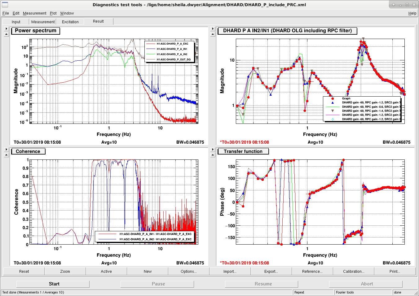
DHARD P
We were having a 1Hz ring up for any gains less than -60 when we first locked, with 30W input and the RPC gain at -1.2. We eventaully reduced the gain of SRC2 P by a factor of 15 (from 15 to 1). Now we were able to reduce the DHARD P gain to -30, which is the nominal value for low noise, and engage the 17Hz LP.
The problem we have is the 0 phase at 1 Hz, and there is a dip in the gain at that frequency for some reason. We could change the dip in the gain by changing the RPC gain, but only to make it deeper. We also found that reducing the gain of SRC2 P (AS_C to SR2) made the dip deeper. This allows us to reduce the gain because the unstable point at 1 Hz drops below unity gain. Screen shot attached shows the OLG measured from the blend, this includes the radiation pressure compensation in the measurement. The measurement shows the loop gain once before we reduced it and turned on the low pass. We have not put the changes to SRC2P or the gain changes for DHARD P into the guardian.
When we have a DARM offset there are the terms that contribute to the ASQ and QPD signals:
ASQ signal: 45_{00}*Carrier_{00} + 45_{00}*Carrier_{10} The first term is due to the DARM offset, and is sensitive to motion of the SRC cavity axis or the OMs. The second term is the DHARD signal
QPD signals (AS_A, B, C DC signals) 45_{00}*45_{00}+C_{00}*C_{00} + C_{00}*C{10}+45_{00}*45_{10} The second term is due to the DARM offset, and is sensitive to the SRC cavity axis and the OMs (on AS A and B). The third term is also due to the DARM offset and contains DHARD signal.
This means that when we have a DARM offset, there is a cross coupling between the QPD loops and the DHARD loop, which depends on the DARM offset. This means that both the SRC2 loop and the AS centering loops can have an impact on the stability of the DHARD loop, and vice versa.
DARM offset/ 9 MHz increase test:
We also took some measurements that we have been wanting to do for a while to understand better where the 9 MHz noise is in DARM, will post results soon.
- reference time: 9:15 UTC.
- 9 MHz increased by 3 dB, 9:21 UTC
- Darm offset reduced for 14.7 mA DCPD sum: 9:28 UTC
- DARM offset reduced for 10mA DCPD sum 9:34 UTC
- 10 mA DCPD sum, 9 MHz driver increased to 25.2 dBm 9:45 UTC (slightly higher noise)
- 20mA DCPD sum, 9 MHz driver at 25.2dBm 9:56 UTC