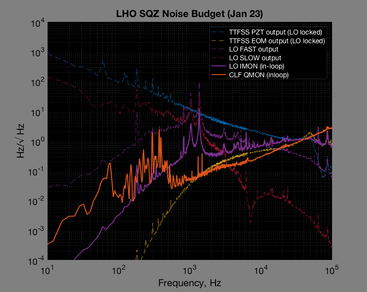
Here's what the overall noise looks like between the two scheme
This is H1 scheme, with 20dB attenuator on 80MHz LO swapped for 10dB, same CLF power used when we measured 4dB (with PSLLO):
And after we swapped, here's L1/original scheme:
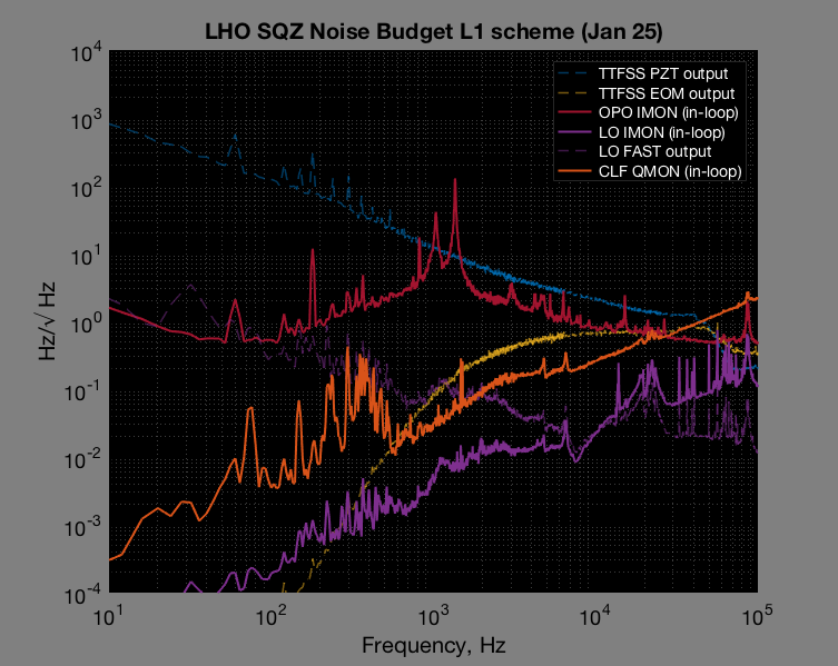
One good news is that I don't think we will see OPO length noise in the IFO anymore as LO is not seeing any of it.
Looking closely at LO phase noise, I don't think this tells the whole story as previous sqz/asqz measurement with L1 scheme appeared to do (just) a little worse. In this plot L1 scheme LO phase noise seems to do much better.
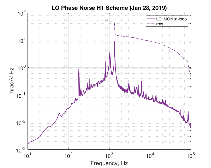
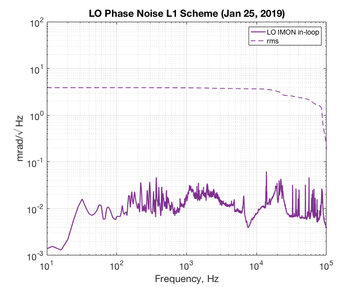
Daniel found CLF correlation < 1kHz with the accelerometer on ISCT6 (alog46712). I'll look at intensity noise next to try to explain noise >1kHz.
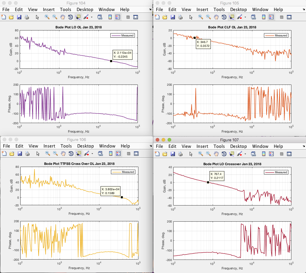
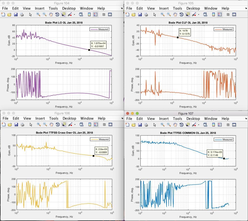
See attachment for transfer functions for both noise plots and L1 scheme noise in mrad.
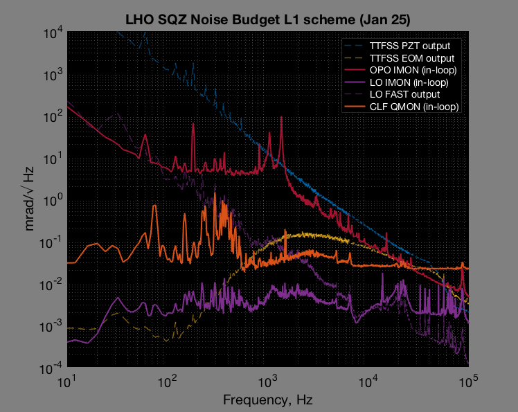

Looks like its pretty well behaved. Since it looks substantially better than LLO's current budget, despite using the same scheme and largely the same hardware, I dug slightly into your provided code.
On your CLF and LO PSDs, I see you are dividing by 2.74 for LO and .340 for CLF, which I'm guessing is the DC voltage of the conjugate phase (you're locking CLF in Q?, why is QMON plotted).
There is an additional factor of 2 on the LO, which suggests you are using the CLF phase sensitivity. As I mentioned in the meeting, I think you should move this factor to the denominator of the CLF to use the LO as the reference sensitivity. This will improve both by 2x. I could be wrong if you are dividing by the pkpk of the unlocked signal or something, I'm not sure what the divided numbers are.
I don't see the factor of 2pi to convert to the phase sensitivity though. I suspect the CLF and LO spectra are currently too small by this factor (netting a factor of pi too small if the above factor of 2 and 2pi both need to be included).
Since the budget isn't decomposed into factors, If you look at L1schemeNoisebudget_mrad.png, you see that there is on the CLF a residual with ~200Hz of 3.14mrad/rtHz (where I've added the net factor of pi). This means your current CLF operation is has ~40mrad RMS of residual noise. The sensing noise of 2e-2mrad/rtHz * pi * (2000Hz)**.5 ~= 3mrad is below that, so the CLF gain could be higher.
Ok, actually I was confusing myself with this factor. I did the derivation again and your code is doing it right, no additional factor of 2pi. I'll have to adjust the LLO phase noise budgets down accordingly (factor of 4pi, 2pi from this, and 2 from using CLF as the sensitivity reference instead of the LO). In this case, the 100-150mrad seen in the IFO at LLO cannot be explained by anything but the excess at high frequencies. Looks like you should be less plagued by this given these plots.
Just to clarify, I used Vpp of unlocked CLF and LO signal to calibrate the spectrum. CLF Vpp calibration is V/rad while LO is V/2rad.