Summary:
We've designed and ordered a custom mask for the ITMY CO2 projector. The purpose is to counteract the higher-order components of the thermal lenses in the recycling cavities that will predominantly affect the sidebands and lead to higher order differential lensing. Two big questions to be answered:
- How well does the mask have to be aligned (and how stable is the CO2 alignment)? Fine-tuning the alignment and the stability of the alignment will be important to monitor.
- What is the expected improvement in sideband imbalance/build-up versus just using the RHs (which is what we're doing right now)?
The installation and alignment of the mask is relatively low overhead. Once aligned, it will remain as an option for the commissioners to explore and further simulations can be performed on expected IFO performance.
Details
The mask is on the DCC at D1900030.
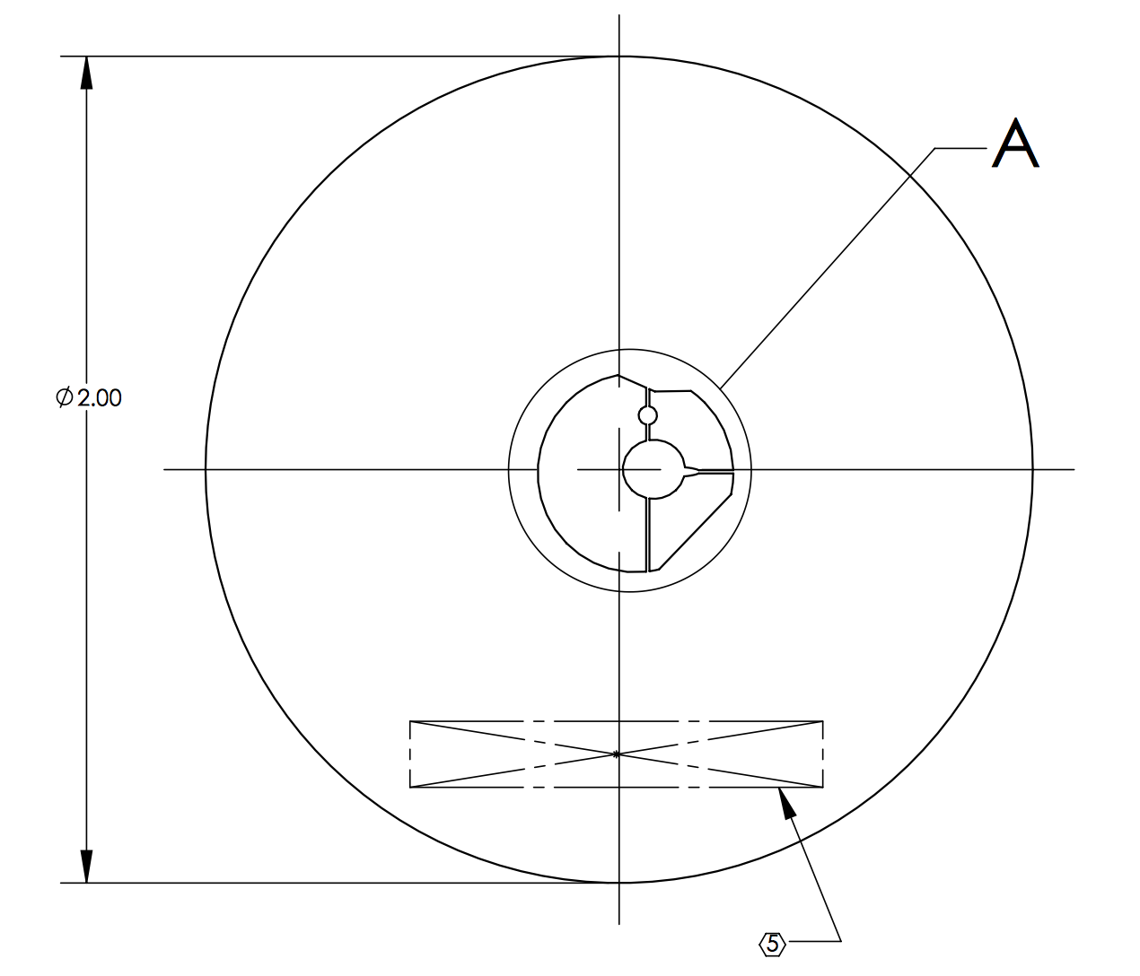
The procedure for finding the optimum mask is as follows:
- Work out the steady-state thermal lens from a 4mm diameter, 10mW absorbing region. We're going to use this and rely on the fact that the thermal response is linear: i.e. the sum of the thermal lenses from absorber A and absorber B is the same as the thermal lens from "absorber A + absorberB": TL(A+B) = TL(A) + TL(B).
- Create a function of N+1 parameters (we used N=317). For parameter a_i, (where i <= N), we add the above thermal lens centered around a point [x_i, y_i] and scaled by a_i. The N+1 parameter adds a quadratic thermal lens from the ring heater. This function is TL_fit(a).
- The points are spaced 10mm apart in rectilinear grid out to a radius of 100mm. Note that in the limit that the spacing is 4mm, we effectively recreate uniform absorption.
- Create the total thermal lens using the data from the HWS (scaled to single-pass) TL_HWS,
- TL_tot = TL_HWS + TL_fit(a)
- Create a function that determines the RMS wavefront distortion of this total thermal lens weighted by the intensity of the TEM00 mode on the ITM
- = sum(TEM00*TL_tot)/sum(TEM00)
- F_RMS(TL_tot) = sqrt( sum(TEM00*(TL_tot - )^2) / sum(TEM00))
- Use FMINCON to solve for the values of a that minimize F_RMS. (see aLOG 46127. )
- FMINCON allows us to be constraints on the parameters a.
- Each of the thermal points was limited to the range [0, 0.1]. The RH was limited 6W of power.
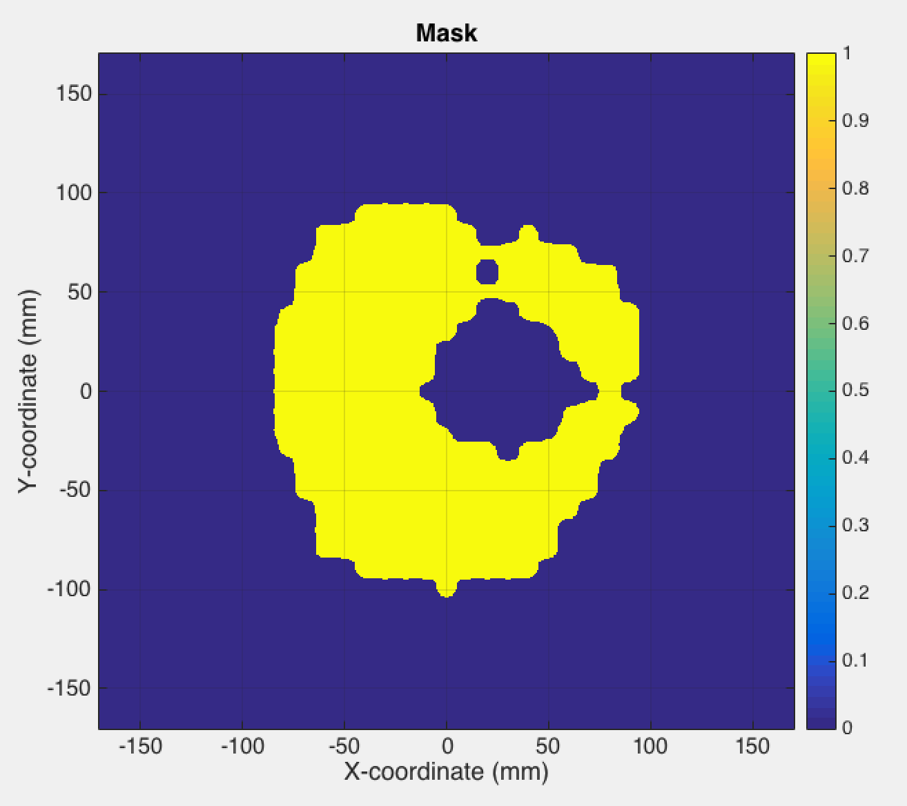
- The solution to a yields the required distribution of heat across the test mass. Since we don't want to create a mask that is a regular series of holes (ie. a diffraction grating), we smooth this by a minimal amount to create large shapes of uniform heating and create an image from this. This image is used then used as the basis for a mask. The image is also made 9% larger in the horizontal direction to account for the fact that the AOI between the mask and the CO2 laser beam is 22.5 degrees.
Results from simulation:
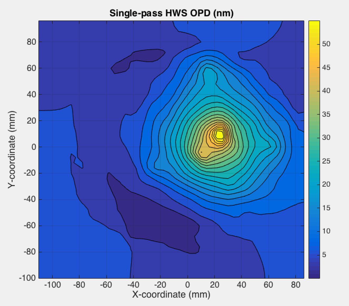
Original heat distribution:
Mask for CO2 laser (at ITM scale):
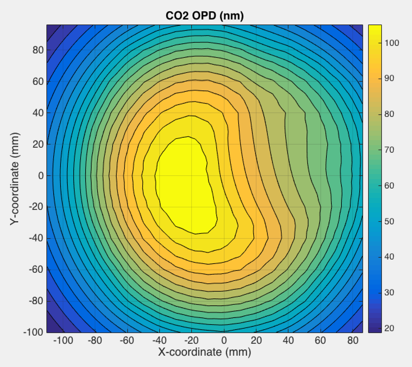
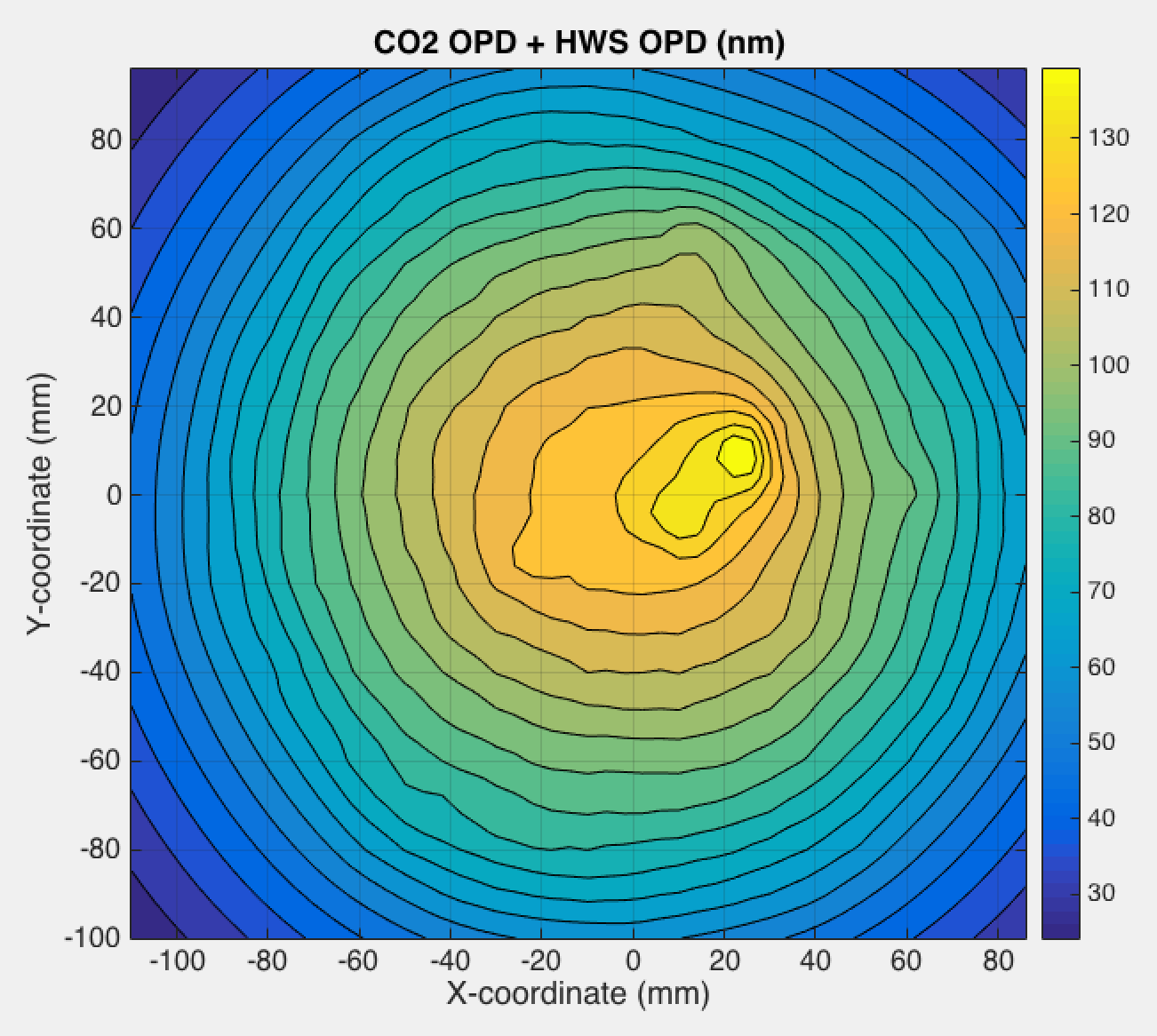
Optical path distortion from CO2 laser projected through mask and imaged into ITM
Optical distortion from CO2 + Self/HWS OPD
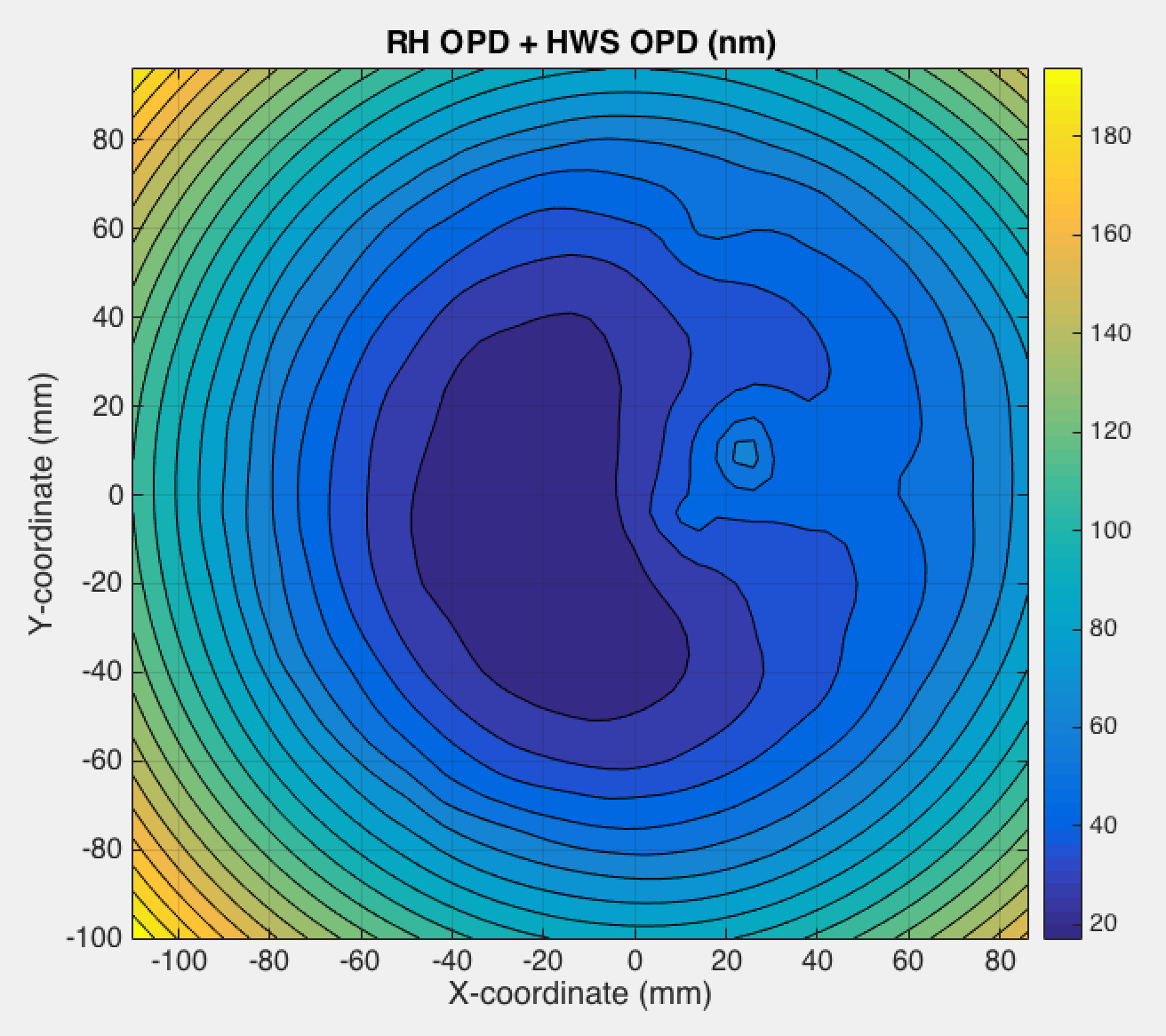
OPD from RH + Self/HWS OPD
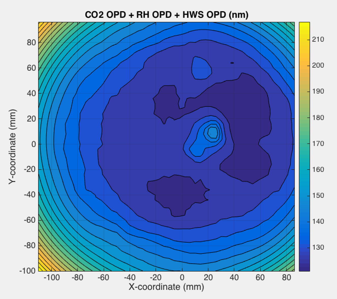
OPD from CO2 and RH and Self/HWS
Alignment
Alignment is a big issue - clearly this will need to be matched well to the existing thermal lens to be effective. A long term drift in the CO2 laser alignment to the test mass was noticed in Q4 last year (Approximately 12 months after the previous alignment). We need to be cognizant of this.
Fine tuning of the alignment will be accomplished by mounting the mask and flipper mirror on an X-Y translation stage that offers up to 3mm of travel in X and Y (corresponding to 63mm of displacement of the heat pattern in X and Y on the ITM with a magnification of 21x).
Magnification
The mask is set up for the nominal magnification of 21x. We should be cognizant of any variations in the actual magnification as this will create discrepancies between the required and actual heat patterns.
Nominal turn around time for a new mask to be machined and delivered is 5-6 business days (including shipping).
Photo of masks.
