craig.cahillane@LIGO.ORG - posted 04:04, Friday 08 February 2019 - last comment - 09:59, Friday 08 February 2019(46864)
Frequency Noise Projections into DARM
I projected frequency noise into DARM using the swept sine TF and broadband noise injection TF.
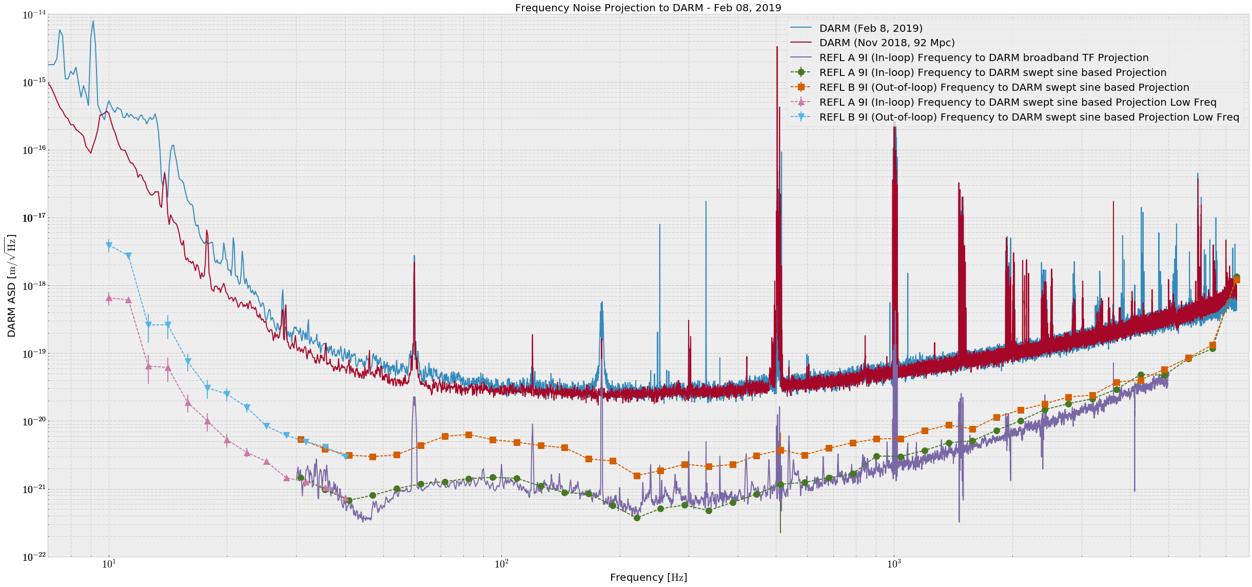
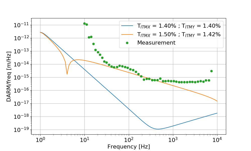
At 80 Hz we are a factor of 5 away from DARM with frequency noise, according to REFL B. Otherwise we are not close except at very high frequencies. (Attachment one)
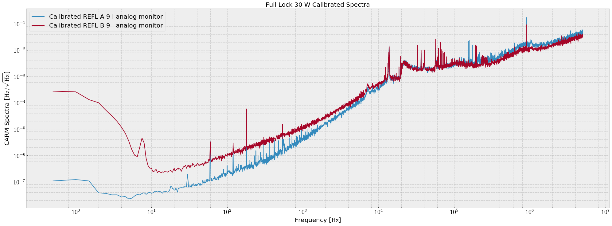
REFL B is the out of loop witness of frequency noise, and at low frequencies (below 2 kHz) this PD sees the shot noise on REFL A, the in-loop sensor. The REFL spectra were taken directly out of the analog monitor of the demod boards, and calibrated with a CARM gain of ~ 10 mW/Hz, CARM pole of 0.85 Hz, and some REFL sensing chain TFs (Transimpedance A = 4900 Ω, (includes demod gain) Responsivity = e λ / (hc), Quantum Efficiency = 0.9) (attachment four). The calibration was not used for the projections.
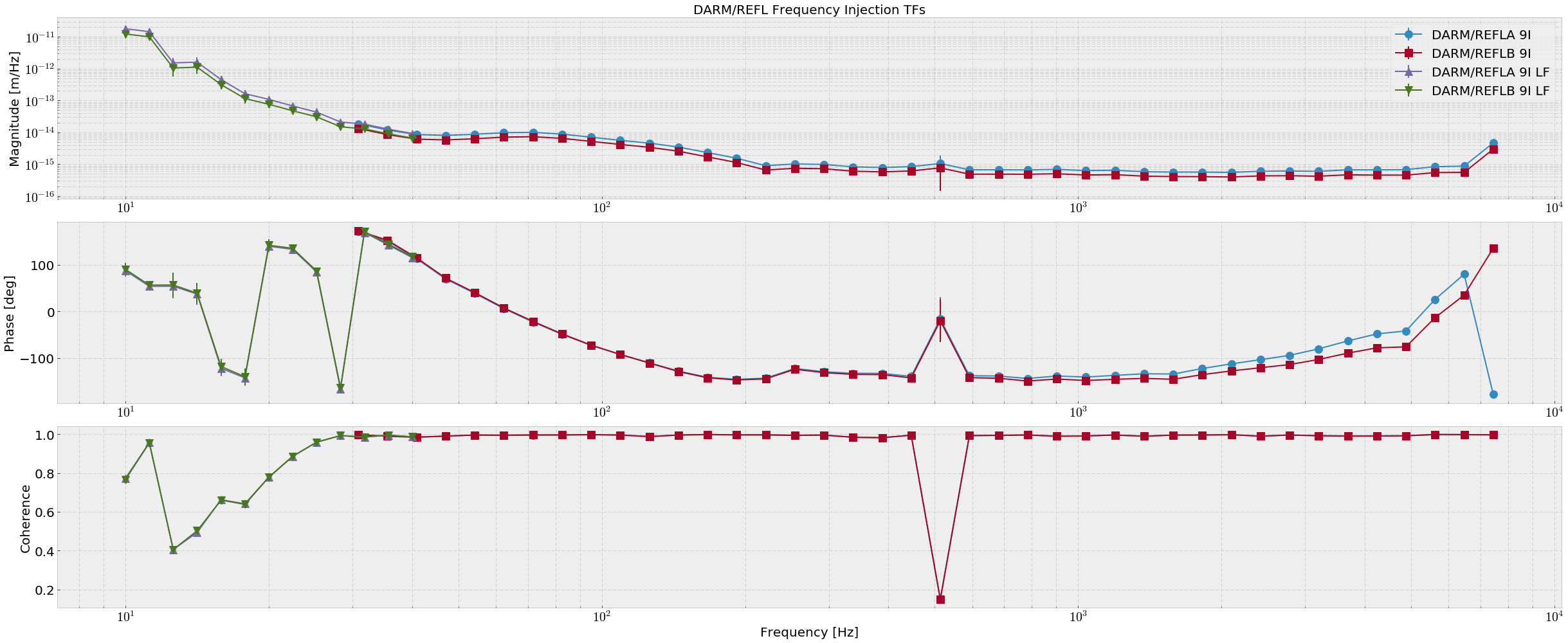
The swept sine TFs were measured from H1:LSC-REFL_{A,B}_RF9_I_ERR to H1:CAL-DELTAL_EXTERNAL_DQ (attachment two). I have previously measured the conversions from the REFL analog pickoff IMON monitors to the digital REFL I ERR channels. I have done this because H1:LSC-REFL_B_RF9_I_ERR is well calibrated into volts, but REFL A is not.
analog REFL A 9 IMON / H1:LSC-REFL_A_RF9_I_ERR = 7.87e-4 # V/cts
analog REFL B 9 IMON / H1:LSC-REFL_B_RF9_I_ERR = 1.02 # V/cts
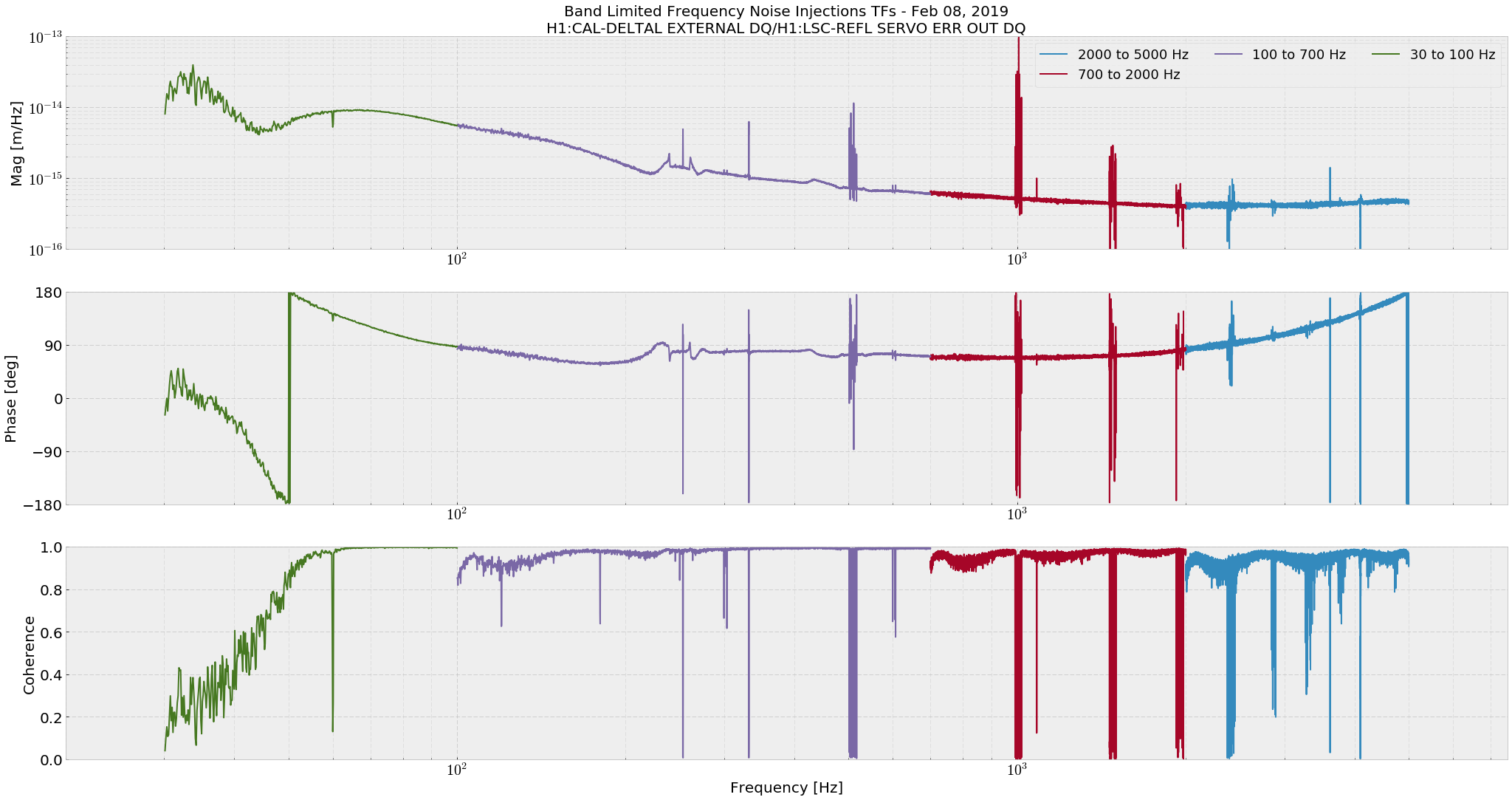
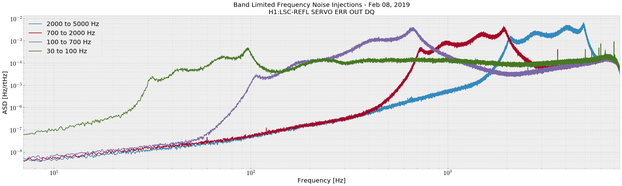
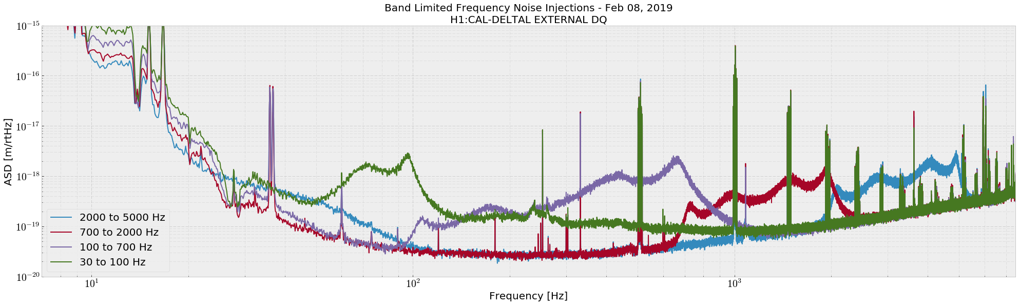
The broadband injection TF was estimated using H1:LSC-REFL_SERVO_ERR_OUT_DQ and H1:CAL-DELTAL_EXTERNAL_DQ (attachment three). The only difference between H1:LSC-REFL_A_RF9_I_ERR and H1:LSC-REFL_SERVO_ERR_OUT_DQ is a factor of 13.1 dB of gain.
The increased laser frequency to DARM noise coupling we see at low-frequency likely follows from this arm power imbalance, and gives rise to the characteristic dip at around 45 Hz where the contrast defect and radiation pressure coupling mechanisms slightly cancel due to the phase difference. Some modeling will be done to explain this curve.
The high frequency flattening of the TFs is still not understood, explained colloquially by "carrier HOMs somewhere in the corner". Anything in the arms would see the CARM and DARM poles and decay at high frequency, and previous tests show that the carrier is likely the main bearer of frequency noise witnessed by DARM at high frequencies.
Images attached to this report
Comments related to this report
Here's a simulation of frequency noise to DARM coupling, based on the same parameters used before (46845, 46683). As for other couplings (PRCL to DARM for example), there is a discrepancy at low frequency, probably due to cross coupling through other LSC loops. And the high frequency flattening in the measurement is probably due to mismatch between the two arms (but in simulation, using the nominal RoCs and adding the ITM lenses do not change the result).
Images attached to this comment