
Power line noise in DARM:
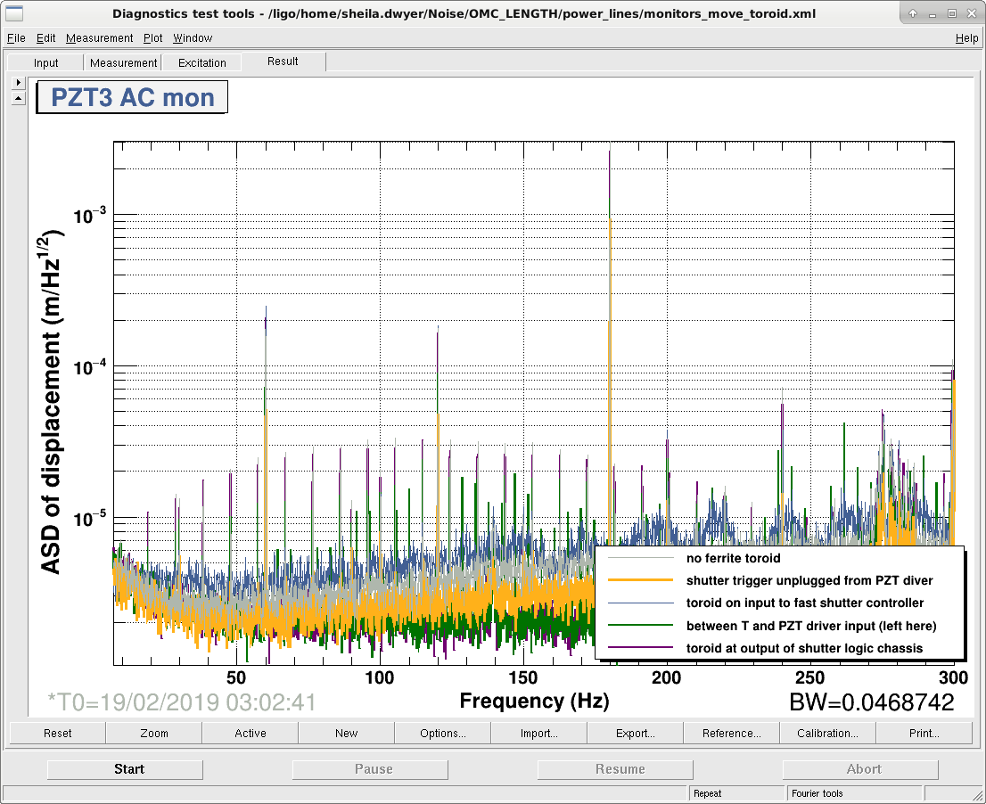
- We tried adding the ferrite toroid to the cable from the fast shutter controller to the OMC PZT driver as pictured here LLO 41394. As Rich suggested I also unplugged the squeezer test equipment that was plugged into the AS racks, and powered down the picomotor controller on ISCT6 using the rocker switch in the back of the chassis. None of this made a difference to the broad power line noise we have at around 60Hz, 120 Hz, and 180 Hz. It also made no difference in the spectrum of OMC LSC I or the PZT HV AC monitor channels.
- During an earthquake Craig and I went back to the rack and tried several configurations watching the PZT AC monitors as we moved the toroid around. THE PZT2 monitor didn't change much for any of the configurations, the PZT3 monitor which has the most lines also had the most dramatic changes for different configurations. In the end we left the toroid right on the shutter trigger input to the PZT driver, this reduced the 180 Hz line in the AC monitor (see second attached screenshot for the variety of noises in the PZT3 monitor)
- It seems like our problem is different from the one diagnosed at LLO in 41394 since we don't see any of these lines in the OMC LSC error signal.
Offset on PZT3 (PZT1):
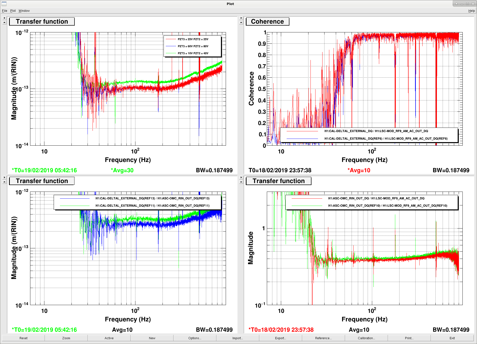
- Jenne and I locked the OMC with 50V applied to PZT3 (which is really PZT1) and 80V applied to PZT2, which should reduce the transmission of the 9MHz higher order mode through the OMC according to Koji's second attachment in: 46667
- We injected 9MHz RFAM using RF AM stabilization box excitation.
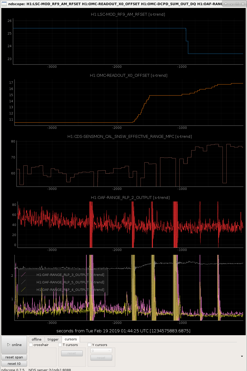
Comparing the same transfer function with and without an offset on PZT3 there is a 20% improvement in the coupling of the 9MHz driver noise to DARM with the PZT offset on.There is about a 20% reduction in the measured coupling from the RF AM driver AM monitor to the noise in DARM with the PZT offset. Some of the reduction seems to be due to to a drift in the amount of 9MHz arriving at the AS port, if we measure the transfer function from the OMC QPD RIN to meters the PZT offset has reduced that coupling by about 15%. In the lock with no offset on PZT3, I tried to move PZT3 around a bit but the coupling doesn't depend very sensitively on the position of the PZT. It might be worth trying this with the 50V offset on PZT3 as well. - The time of the injection with no offset on PZT3 was 5:42:16 UTC Feb 19th, with 60V on PZT3 the time was 23:57:38 UTC Feb 18th.
- Georgia also repeated the tests from 46831 with the PZT3 offset on, and off.
OMC ASC on dithers:
- While Georgia was changing the DARM offset, we noticed that the 100-400Hz BLRMS was responding to her change. It turns out this was because this monitor was dominated by lines in DARM.
- We trned off the LSC dither lines which have been used as monitors since December, and removed them from the guardian. We also widened nothces and adjusted the frequencies of some of them so that the 100-400 Hz blms is now measuring the level of broadband noise.
- The reason that the BLMS channel was responding to the DARM offset change was that the optical gain change is not completely compensated by the quadratic scaling done in the OMC model. The optical gain was changing by 5% more than that scaling was compensating for.
- We wondered if the change in the DARM offset (or the 9MHz modulation depth) was changing the lock point of the OMC ASC, which is still using QPDs. Georgia tried adjusting the QPD offsets a little bit.
- The kappa c monitor seems not to be working, so we made two of our blms channels into narrow bandpasses for the pcal lines, and tried to use those as montiors for the optical gain, but they are rather noisy.
- I tried setting the OMC back on the dither alignment, which is working fine so far and not close to saturating the suspension. I only moved to the dithers about 2 hours into the lock, so there may be a time earlier in the lock when we can't use them.
- While the dithers moved the OMC alignment, they didn't improve the optical gain.
4.5 Hz instability in DARM loop:
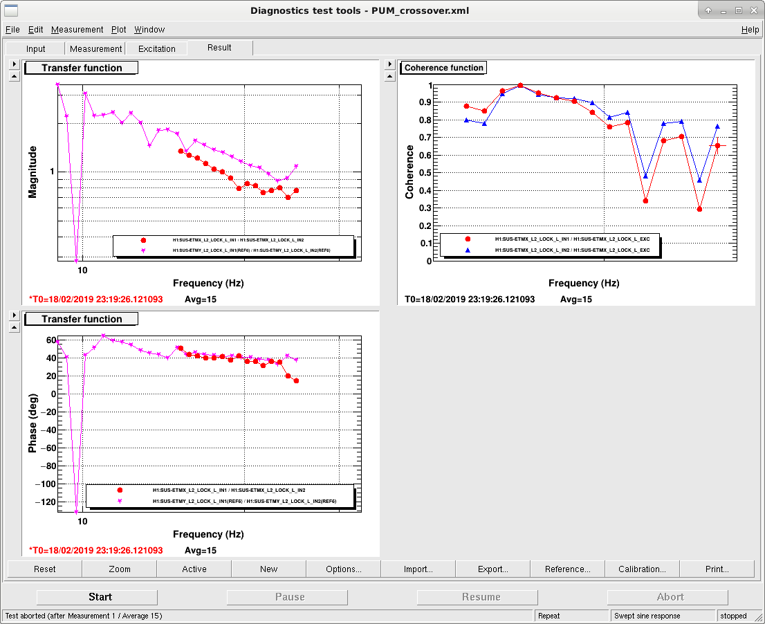
- We had one lockloss where the DARM loop seemed to go unstable at 4.5 Hz. The pum cross over has a 0 phase margin around that frequency according to the model here, but we think that we should not have any cross overs there according to the model.
- We made a quick measurement by injecting into ETMX L2 (attached screenshot), which agrees well with the model from 25-10 Hz.
- We also looked at the drive spectrum of all three stages, and tried a small increase in the L2 LOCK gain, which did slightly reduce the RMS drive and reduced the small peak in the drive amplitudes around 4.5 Hz. We have added this small gain change (15 to 17 Hz) in the guardian.
- We lost lock once more with a similar 4.6 Hz instability in DARM, (with the gain of 17 in place) about 10 minutes into a lock. I wonder if there is something about the ADS loops slowly converging that is having an impact on the DARM loop. We may need to spend some more time on the stability of this crossover, next lock I just waited for the ADS to converge before transitioning the DARM actuator.
- The guardian is now doing the switch from ETMY+ITMX to ETMX in one step, rather than two.
I went through some of the ADS things in LOWNOISE ASC to try to make the ADS a little less confusing to me.
- I set all the amplitudes to be the same (they were all within a factor of 2 or so of each other anyway).
- For PIT3 and YAW3 we had a signal gain of 0.1 canceled by a demod I gain of 10, got rid of these two gains and added a filter module which will be engaged earlier engage soft loops to compensate for the higher signal gain and keep the loop gain the same as it has been.
- For the other loops I also have found it confusing that the I gain was not the same as the Q gain, so I moved the compensation for the dither amplitude reduction into filters as well.
- For PIT4+5, I also added additional gain, because these loops were taking a very long time to converge. (Now PIT4+PIT5 have the same gains).
- For YAW4+5, I moved the gain into filter banks, decreasing the gain of YAW5 and increasing the gain of YAW4 so that they now match each other.
We aso reduced the CSOFT P gain in lownoise ASC from 30 to 20 as Danny was doing yesterday, this is in the guardian now.
We also set the DCPD NULL matrix elements to be the same as the sum matrix elements but with a sign flip. Stefan had set them according to this procedure: 45734 but that isn't compatible with the online DCPD cross corelation calculation, so for the moment we are setting them back to see if we can get some good data for the cross corelation measurement. We also found that there was a gain of 1.2 in the inverse sensing function, which we needed to copy for the null stream filter. Now we are getting more sensible results from the cross correlation.
With regards to the OMC PZT offset:
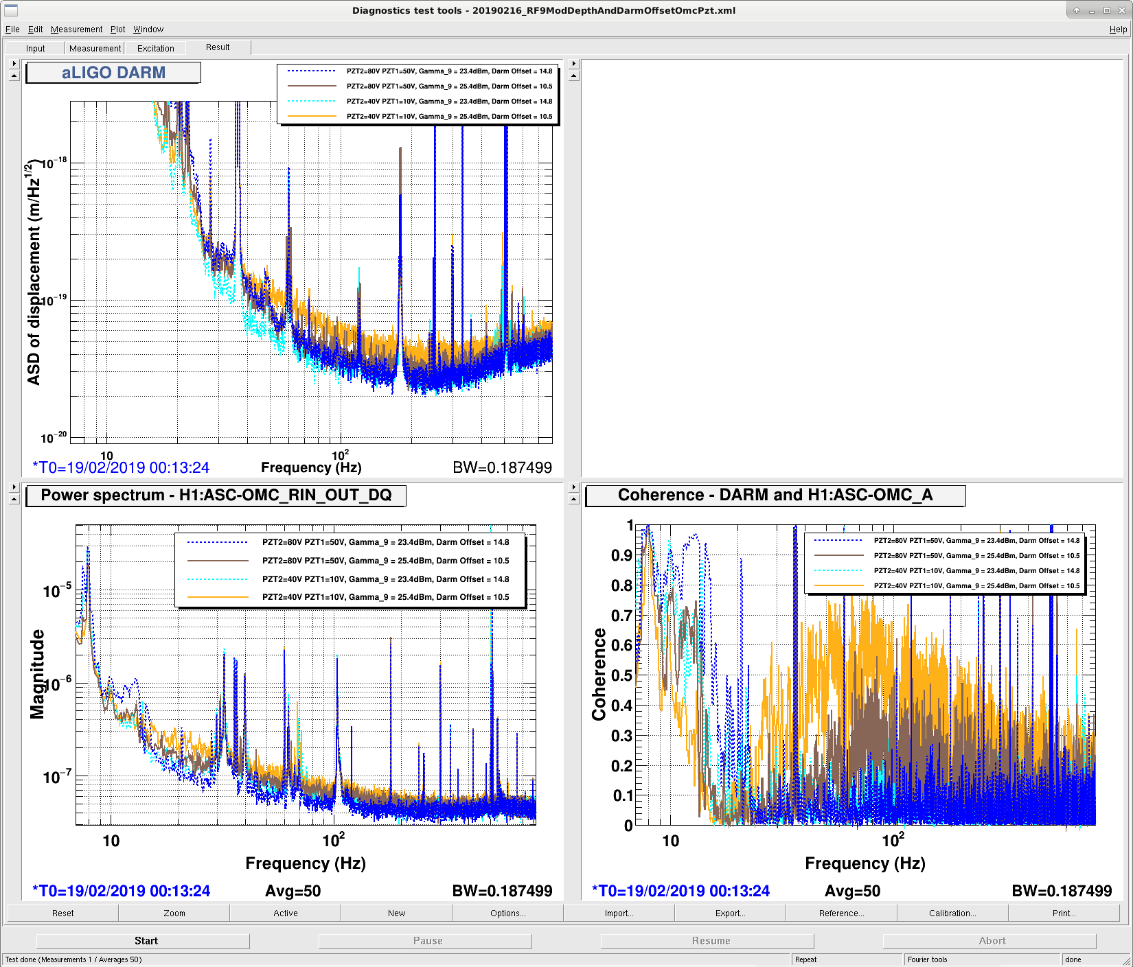
We locked with 50V on PZT3, 78V on PZT2, this combination of PZT voltages should reduce RF9 9th order sideband that gets through the OMC. Looked at DARM, the OMC QPD RIN and coherence between DARM and OMC QPD RIN, as in alog 46831. Made these measurements for nominal DARM offset and RF9 modulation depth, and low DARM offset and high RF9 modulation depth.
It looks like the coherence better with the higher PZT voltages in the case of the driven measurement. Dashed lines in the first attachment are nominal rf9 modulation depth and darm offset. Full lines are with extra modulation depth and reduced DARM offset to increase RF9 coupling. Brown and blue are [50,80]V and cyan and yellow are [10,40]V for [PZT1, PZT2]. Another thing to note is the RIN on the QPDs is increased between these two measurements, we'd expect to be independent of the PZT voltages, so maybe the fluctuations in 9MHz RIN between locks is confusing us.
Other locking notes:
- While changing the DARM offset we found a slightly DARM offset improves the BNS range, and the noise at low frequency, see second attachment for range and some BLRMS for different DARM offset and RF9 modulation depth. With low DARM offset there are more scatter-like glitches in the spectrum.
- We wanted to power down from NLN and lock on a different OMC PZT resonance. Tried opening the ISS 2nd loop (from ISS DC coupled) while in nominal low noise, lost lock immediately.
- We tried relocking with the high OMC PZT voltages but lost lock after 2 mins at NLN due to what looked like a soft loop ring up described by Danny on Sunday.
Well, it's back to the drawing board on this one. Thanks for doing the test, it helps eliminate the possibilities. When I get there next week, I will measure the common/differential mode attenuation of the torroid that was used to be sure it has some useful attenuation in the audio band as intended. Could still be that the LLO and LHO torroid materials are different and has high permeability at different frequency bands. Feels a bit like grasping at straws now though.