craig.cahillane@LIGO.ORG - posted 02:18, Monday 25 February 2019 - last comment - 20:03, Monday 15 April 2019(47113)
Modulation Depth Measurements
Craig, Georgia
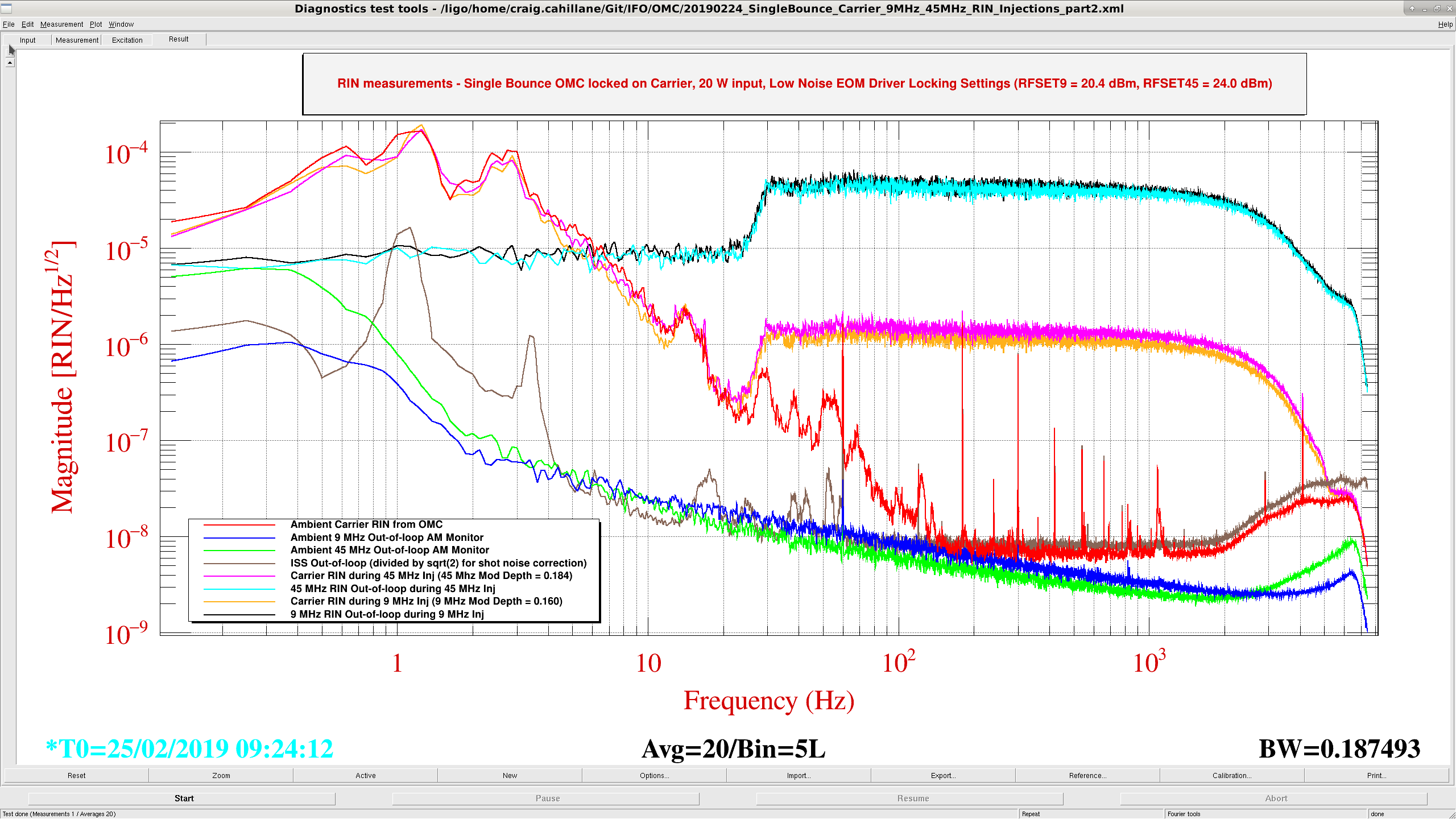
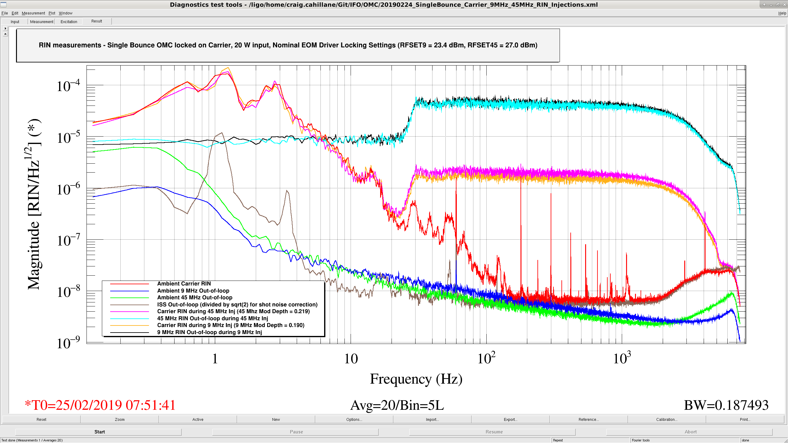
Today we locked the OMC on single-bounce carrier with 20 W input and injected large sideband intensity noise to measure the modulation depths for locking and low noise settings.
Results
Sideband Locking EOM Driver Slider Value [dBm] Low Noise EOM Driver Slider Value [dBm] Locking Mod Depth Low Noise Mod Depth
---------------------------------------------------------------------------------------------------------------------------------------------
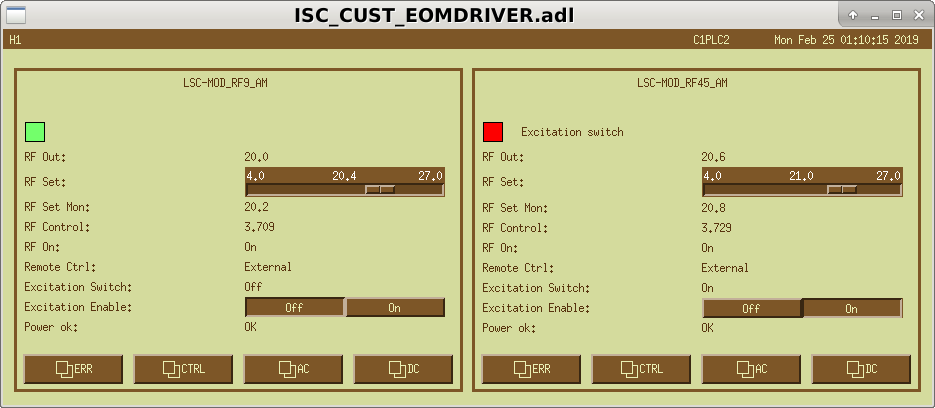
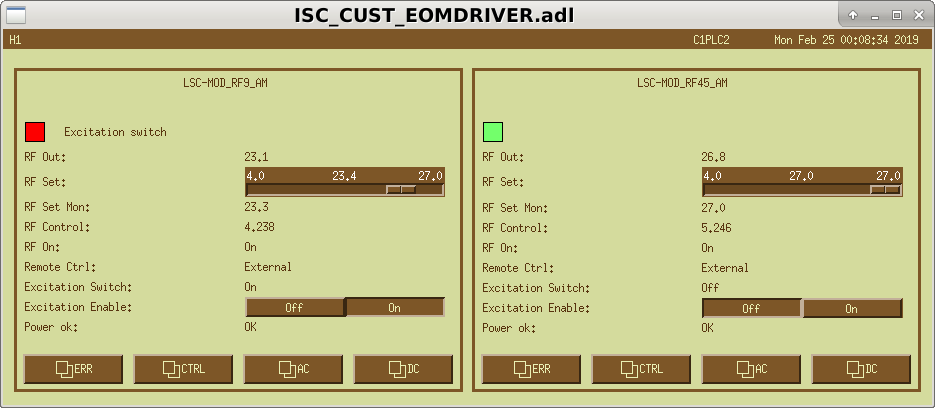
9 MHz 23.4 20.4 0.190 0.160
45 MHz 27.0 24.0 0.219 0.182
Method
A simple comparison of the carrier and sideband RINs when injecting.
RIN0(f) = Γ2 RINsb(f)
We know that we can trust the 9 and 45 MHz RFAM monitors when we inject high broadband noise in the EOM driver.
At the same time, if we inject enough sideband RFAM, the carrier RIN should show through in the OMC transmission.
All injections were amplitude=10, ellip("BandPass",4,1,30,5000) through the LSC EXTRA AO 3, which is connected to the front of the drivers.
Reason
We've been running several 9 MHz RIN tests. It is good to know, for some high level of sideband RIN, the level of carrier RIN we expect.
Old EOM Driver alogs
Koji installation
Daniel boost
Images attached to this report
Comments related to this report
These numbers are likely wrong because we cannot trust the calibration of the RFAM monitors when we move the sliders away from nominal.

Math
I double checked the math here, I think there is a factor of -2 missing:

If P0 = Pc + 2 Ps, where P0 is initial power, Pc is power in the carrier, and Ps is power in a single sideband.  If we require P0 to be constant, then taking the derivative wrt modulation depth gives
dPc = -2 dPs

Pc = J0(Γ)2 P0 ≈ P0
Ps = J1(Γ)2 P0 ≈ Γ2/4

RINc = dPc/Pc
RINs = dPs/Ps

RINc = - Γ2/2 RINs